lifan 150 twin output stator mod

Mini Dirt Bikes & Pit Bikes Forum

Help Support Mini Dirt Bikes & Pit Bikes Forum:

This site may earn a commission from merchant affiliate links, including eBay, Amazon, and others.

1fifty1wheel

Well-Known Member
Joined
Mar 14, 2008
Messages
338
Reaction score
5
Location
mid coast SA
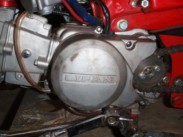
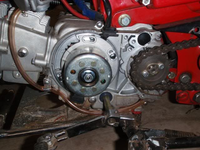
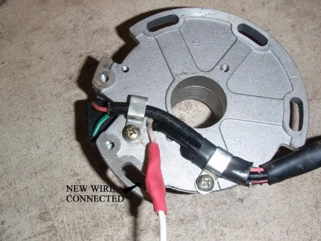
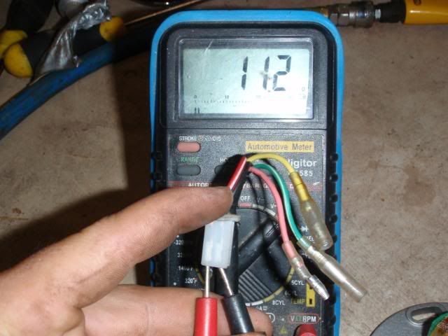
Well as promised, here is the mod to give two usable output wires from the lifan 150 which originally only has one.

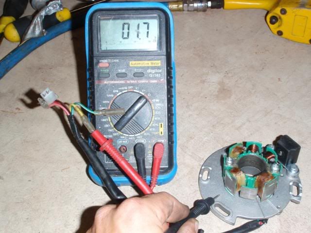
I have yet to connect these to the regulator but will update when done with the results. As for max output, this I'm unsure.

Here goes......

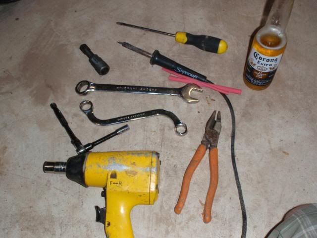
Firstly, the tools required ...

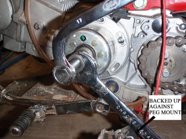
17mm & 22mm spanner for the rotor puller.
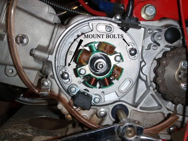
8mm socket for cover bolts.
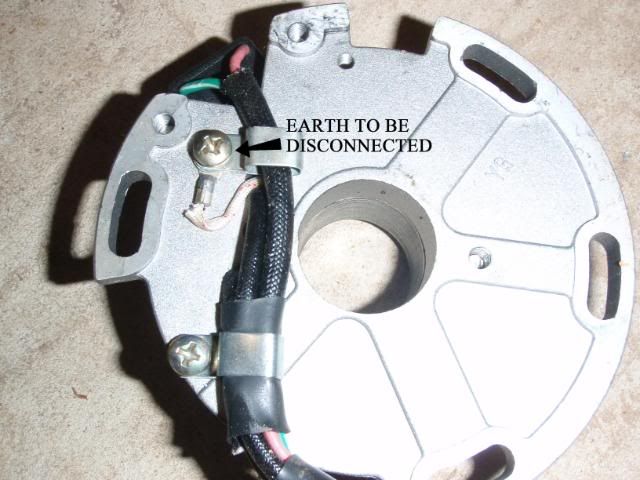
Phillips head screw driver for stator earth.
soldering iron.
heat shrink.
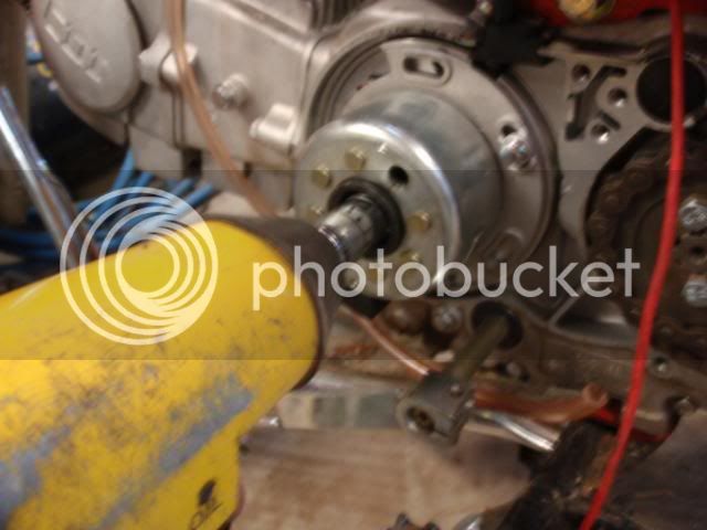
rattle / impact gun with 14mm socket.
pliers.
your choice of refreshments.

PC020515.jpg
 
Last edited:
To get this to work, the basic idea is to remove the earth of the auxiliary coil and use this as another feed.
Because of the way AC voltage behaves means this is possible.

Lets begin.

First off, remove the LHS (left hand side) engine cover. 3 x 8mm bolts.
PC020492.jpg


Removed...
PC020493.jpg


Remove the 14mm nut using your impact / rattle gun. Don't forget to remove the washer too! (failing to remove the washer means it could potentially catch and damage threads when removing the rotor)

PC020501.jpg
 
Install your rotor removal tool, don't do the main body too tight as it makes removing the tool from the rotor difficult.

Also note the tools main body and the rotor have a left hand thread.

This particular one needs a 22mm spanner for the main body and a 17mm spanner for operation.
I back up the spanner against the peg mount to make things easier.

PC020503.jpg


Because the rotor is magnetic, I highly recommend place it on a clean surface free of potential metal shavings.

This is what you're left with..

PC020505.jpg


At this point I'd ensure you positively mark the relation of the backing plate to the engine case to keep your original ignition timing. The original paint marks around the two 8mm mount bolts will not do the trick!
 
Last edited:
Once the position is marked, remove the two 8mm mounting bolts from the backing plate and remove the stator assembly.

Here is a shot of the rear of the backing plate and stator assy.

PC020508.jpg


It shows the earth which will soon become the second aux feed.

Remove the Phillips screw and and the terminal, reinstall the screw with the cable clip.

In the next photo you may notice a large lump at the join. This is because i left the terminal on and soldered the new white wire directly to it. The reason for this was i wasn't sure if this would turn out and didn't want to have to redo the terminal.

It shows the new wire connected to what once was an earth soldered and covered in heat shrink.

PC020509.jpg
 
A few shots of the resistance values prior to the mod.

Auxiliary coil resistance
PC020506.jpg


Ignition coil resistance
PC020507.jpg


checking i have a good connection and haven't broken any wires.
PC020510.jpg


The last also shows the new wire running through the original sheath. i slid the grommet towards the end of the loom then fed the wire as far as it would go. Then slid the grommet back towards the stator and continued to feed the wire through. (if that makes sense?)
 
Last edited:
1.7 ohms to me seems pretty low on the auxiliary coil but right until disassembly it was running the lights without a problem so must be fine.

Anyway, reassemble in reversal ensuring the stator loom isn't crushed and your timing is where it was originally set.

PC020511.jpg


I fitted a Honda engine cover in place of the Lifan unit, the two main bolts line up perfectly but the smaller rear one does not. I'll sacrifice this for the chain guard and Honda badging!

PC020514.jpg


Once tested with the meter, both feeds do indeed have power. they both have around 13 volts AC at a high idle.

PC020513.jpg


Hoping this answers a few questions for some.

I'll update this in a while when i get around to hooking it back up to the regulator and can monitor battery charge. It will be a while but looks promising.

ENJOY!

J
 
Last edited:
Random bits of gold......

I had read in the past you are limited to 55watts output on the 150's auxiliary coil. I couldn't confirm or disprove this. How do you find / work out max output?

The original auxiliary output (yellow) has enough power to successfully run a headlight and taillight, just as usual, little dim at idle but plenty of brightness while riding. I'll put the globe wattages here later....

This mod only takes 45 min's - 1 hour. It took me an 1 1/4 hrs to do, thats with setting up for and taking photos. Oh and drinking a 6er doing it.

Just let me know if I've missed anything during teardown and I'll add it.

Any feedback is more than welcome and I'll answer any questions i can.
 
Last edited:
Just let me know if i've missed anything during teardown and i'll add it.

Any feedback is more than welcome and i'll answer any questions i can.

Very good , sticky that

will come in very handy ,top effort
 
Excellent job mate,im eagerly waiting to see how this goes and to know if this modification makes the head light usable at night.
As mentioned in my P.M to you im itching to get a bit more squirt out of my RX and im hoping this mod will provide enough juice to make the head light usable at night. Ive also recently been in contact with Motor Rego at Regency Park and spoke to a vehicle inspector who assures me i can swap out my 125 with a 150 and all i have to do is notify motor reg of the engine number change and displacment increase and a vehicle inspection wont be necessary as its such a small cc increase.
Any idea on when you can test this at night to indicate head light brightness?
 
The headlight can succesfully be run directly off the original yellow output. This is how i was running it previously.
Would say it'll be a couple days minimum before i get a chance to get in the shed again. Will update the thread as sson as i have a chance.
 
it wont work
once the rectifier/regulater[changes ac to dc power] goes on it will reduce the voltage
why are you doing this?
 
Its been done successfully by others (apparently). Until i connect it I personally can't clarify but all the meter readings are there to say it will.
I have no doubt it'll be successfully.

Why do it?
1. Because i can.
2. Its in a Ct110 and i want to run the lights live and have a chargeable battery for other auxiliaries, indicators, horn, etc. Just as Honda wired the bike when built.
 
fair enough to run like original.
i would put both into the reg/rec and then run all the lights out of the battery .
the original system is more complex
2 outputs = 2 voltage regulaters .
a good system will give consistent light reguardless of engine revs ,
and less bulb breakages .
 
2 outputs, 2 regulators? sort of.
For those who don't understand regulators, the best explanation i came across

fatcaaat: Yellow power line is walking down the street and wants to go into the bar. He goes in through the yellow doors, has a drink, and comes out the way he came in through the yellow doors and continues on his way...but is slightly altered. He is no longer the wild AC but the mild and inebriated DC

Next scenario. Yellow power line is walking down the street and he sees his lady friend waving him over to come in the house for some fun. She invites him in through the white front door. They go in and have some fun, but he's now a little worn out and has a little less energy than before. So as to not show she's a ****, she doesn't send him back out the front door...she sends him out the side red door. He then heads home to sleep off the good sex and recharge.

I know a good system will give consistent light at all revs but the ORK supplied and fitted with the Lifan 150s are not designed to run a full electrical system. I'm more than willing to have a slightly dull light at idle when not moving, vs a bright light at idle and an engine that struggles to build revs.

This Mod effectively doubles the small output of the auxiliary coil to something more usable by utilizing what would normally be wasted to earth. Strange thing is some of the guys i used to work with in electrical engineering couldn't see the concept.

Will be the same as was, yellow to yellow on regulator which lights are already connected.
New white to white on regulator for the charging side. This means i get a better light while riding than i would just running off the battery.
 
Last edited:
hmm looks good .hope it works thanks for the lesson .
ive not fiddled with outer kits that much .
not the same as std ign?
 
ORKs are more rider friendly and tuneable than an IRK or standard ignition. Same concept, slighlty different execution.
 

Latest posts

Back
Top