Max current of Lifan 125 1P52FMI

Mini Dirt Bikes & Pit Bikes Forum

Help Support Mini Dirt Bikes & Pit Bikes Forum:

This site may earn a commission from merchant affiliate links, including eBay, Amazon, and others.

skywriter

Member
Joined
Aug 16, 2015
Messages
14
Reaction score
0
Hi there! Can anyone explain me what is the rated current of magneto of 1P52FMI engine?
I'm stuck into discharging of battery when using head light. Discharge current is 1.4A
while current consumed by the light is 3.5A.
So I wish to check if magneto coil is OK or maybe I should try to install second voltage regulator in parallel.
 
Welcome to Minirider's.
First up, make sure you drop in here and Introduce Yourself.
http://www.miniriders.com/general-chat/20824-introduce-yourself.html


Most of the china stator's you should be able to pull 50 watt's from, which is bout 4.5 amp's.
At approx 2500 rpm and above you should get about 13.8 volt's out of your regulator/rectifer to the battery.
This will have the lighting dull a little at idle, as your battery will be receiving about 12.6v minimum.


Is it on an electric start engine ?
So the stator look's like this one ?

20076251444846762.jpg


To check your lighting/charge coil on your stator, unplug your stator wiring from the main harness, andgrab a multimeter and set it to 200 Ohms.
Now put one probe from the meter to the yellow wire from the stator, and the other probe to the white wire,
It should read about .8 Ohm's +/- 10%, temperature will affect the reading's, they're normally tested at 25°c


Cheer's, Craig
 
About me.
I don't know how it looks like, because I didn't disassemble it yet.
I have measured the resistance of coil. It is 7 Ohms (not .7).
0.8 Ohms seems to me too small (if it was). It is close to nothing. The same time, if the coil was teared or burned, the resistance would be infinite. Isn't it?
Also I have measured AC voltage and current with connected 35W lamp (without regulator). Meter show me 9V 4.6A when engine is warming up (choke = on). I don't know the exact RPM, because I have no RPM meter.
9V seems to me very small. Is it? The same time, why it is 9V and not 0 (if magneto was have beed broken)?
 
Last edited:
May be the guy who assembled the bike, muddled the wires and connected spark coil to the light? Should the coils in a stator be different by voltage and current?
 
A single 12v 35w bulb should only pull 2.9A of current to work.


What colour wire's do you have for the lighting?
Is it a one yellow and one white wire ?
Does it run through a regulator/rectifier like this and go to a 12v battery ?
If so, is the battery fully charged ?
How many volt's do you get from the stator with the engine running and lamp disconnected ?

rectifier_d_03.jpg
 
Initially the lamp was connected to the battery and the battery was connected through the voltage regulator. In this case the battery was discharging when turning the lamp on. The current of discharge was about 1.4A.
To measure the AC current from the stator I had connected the lamp and the meter to the jack with disconnected regulator (see attachment).
As I mentioned earier, the meter show me 9V 4.6A when engine is warming up (choke = on), with lamp.
Without lamp (no load, open wires) the voltage was steady 11V on warning up (choke = on),
and raised up to 20V when I temporarily turned the gas to almost highest RPM.
Both AC wires are yellow.
But what surprises me most of all is that the resistance between each of AC wires and the frame (ground) is about 14 Ohms.
According to the schematics found on internet (see attachments), the coil must be isolated from the ground. Must it?
 

Attachments

  • IMG_20150908_155112.jpg
    IMG_20150908_155112.jpg
    67.5 KB · Views: 9
  • lifan_125cc_wiring.jpeg
    lifan_125cc_wiring.jpeg
    191.9 KB · Views: 16
Last edited:
That wiring diagram you linked isn't correct for the way the lighting/charge coil's are wound.
The lighting coil is earthed at one end, then the winding's go around the core, just before the winding's stop there is a wire soldered onto the copper winding, then say another 20 or so turn's of copper before the wire to the main harness is soldered on.
So reading thee voltage off the 2x wire's one will read high, eg 16v-20v, and the other will read around 4v-6v.
The lower voltage wire is the trigger wire, it tell's the voltage regulator when to work (exciter wire).

I have seen a couple of different wiring set up's and i have wired my sons' dune buggy the same as your bike.
It hasn't had a problem with flat battery's or light's since we bought it a few year's ago.
But i have swapped the standard bulb's for high power Led's, the lighting is much better and draw's a lot less current.
There are some decent led spot and flood light's available now too
I used one of these 27w Cree led work light's on my old Atomik Fuse pit bike, cost me about $20 including delivery
There's more pic's in my Atomik Fuse build thread (link is in my signature, same with the dune buggy)
They only draw 1 amp, you can get them in a square configuration too
27W LED Spot Circle Work Light Thin Case FOG Lamp OFF Road Truck SUV 4X4WD WUK | eBay
And the 48w cree led light's have come right down in price too now
48W 3200LM 16LED Bright Square Solid Aluminum Work Waterproof Light Beam | eBay

27wledfloodlight.jpg


27wrear.jpg


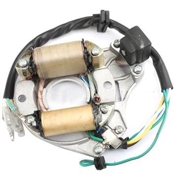
This is what your stator look's like, the lighting/charge coil is the top one in the picture below
The coil on this one use's a yellow wire and a white wire to the reg/rect.

51nErDtqTpL._SY355_.jpg


My shed is locked up atm (it's after 1am here), but if you'd like i can test the stator on the buggy in the morning and let you know if there's any reading's from the stator to earth.
 
Thank you for your review about the LEDs. Anyway, the link to Dune Buggy in your signature lead to the 'Page not found' page =)).

I've already replaced the bulb (because it lights so weak) with LED similar to this one.
It consumes about 3.3A, which together with back light and front panel results in 3.5A.
With this LED light turned on, my battery discharges with about 1.4A (choke = on).
To test AC current and voltage I have used the bulb rated 35W, because the LED is installed under the front pane and it is hard eject it.
Would you be so pleasant to measure the resistance between the coil and the earth?

According to my knowledge, there is no practical reason to connect the coil to the earth.
Because the coil gives us AC current, where the earth is involved into DC current circuit (which feeds the battery, the turning light LEDs, the horn, and the digital panel - they all are fed by DC current). In almost any application (including cars) AC circuit is isolated from DC circuit (in cars this isolation is built in an alternnator, which gives us rectified DC current). If it's not the case for a pitbike, then I want to understand, why?!
 
The regulator/rectifier change's it from AC to DC, the same sort of thing that's inside most automotive alternator's.
Some pit bike wiring use's AC for the headlight power, the positive wire to the headlight switch is tapped into the higher voltage wire from the lighting/charge coil just before it reach's the regulator/rectifier.
The head light voltage is regulated by the wattage from the headlight bulb.
But if the bike is ridden at higher rpm's most of the time, the bulb's fail prematurely due to excessive voltage.

The link in my signature for the dune buggy thread is fixed now too.
 
There are 2 different setups used depending on your setup. If you have 2 yellows coming from the stator you need a full wave rectifier, if you have a yellow and a white wire you need a half wave rectifier. With the half wave set up the coils are earthed as mentioned above, so effictively you have 2 windings (yellow and white), one can be used to provide straight AC for lights and the other rectified for charging
 
Thank's for that bit of information motodevo, it definately clear's thing's up, + rep's mate !
I just seen your post's on monkeybikeoz too :thumbup:


So skywriter, disregard my post's above, except the last one.
they relate to a lighting/charge coil that has a yellow wire and a white and run's a half wave regulator/rectifier.

You should be running a full wave regulator/rectifier like this one


There are some reg/rect's that look the same as the half wave reg/rect's too,
but i haven't tried testing them against each other to work out which is which in those case's.

With your lighting coil showing resistance to the frame/earth, i am guessing that there is either a shorted wire somewhere in the actual coil winding's, or the insulation on your wiring between the coil and your reg/rect has rubbed through and is touching metal somewhere and is earthing out.
You will need to remove the side cover off the engine and check it out further.
The stator is screwed onto the inside of the cover, so no need to remove the flywheel to check it out.
If you can find the short then you may be able to insulate it and it may work properly again and give you full voltage to the battery/light's
If you can't find the short then you will need to replace the stator, or coil depending on what type it is


Your full wave stator should look like one of these


Unfortuantley, even though chinese motors have gotten to a point where they're fairly reliable, chinese electrics are still shyte when it comes to charging/running lights. There dont seem to be any rules to what goes what and you seem to get whatever type of stator. I like the 6 pole stators in your post above, they are usually found in elec start engines as well as kick only motors and will bolt straight to a crf50 stator plate which is handy, they seem to produce more wattage than the 2 coil version.
 
I tested my spare 6 pole full wave stator today, but forgot to post the result's
Across the 2x yellow wire's, my multimeter (set at 200 Ohm's) read .9 Ohm's
There is an open circuit from each yellow wire to earth (stator backing plate)

So with your stator getting a reading of 14 Ohm's from the yellow wire to earth, either one of the winding's has rubbed through the protective/insulating laquer and is shorting out onto the plate's through the middle to earth.
Or one of the yellow wires' insulation has rubbed through on something metal and exposed the copper wire's inside and now has shorted out to earth.
There is possibly corrosion on the exposed wire's now which has made the resistance so high (7 Ohm's)
 
Today at last I pulled off the cover. The stator has 6 coils. There are one white and one yellow wire go from the stator to the voltage regulator.
The resistance between the yellow or white wire and the core metal plate is less than 1 Ohm.
Does anybody knows the dedication of the other wires (namely: green, red-black, blue-white) to better understand the schematics? Or may be there is schematics of the coils wiring out there?

Also I'm interested in opinions about the lubrication of the valve's chain.

OFFT: Why the button "Post new thread" has disappeared in the 'Electrical' chapter?
 

Attachments

  • IMG0026A.jpg
    IMG0026A.jpg
    304.6 KB · Views: 10
Last edited:
I have measured the resistance again, and with more precise meter.
The resistance between the green and the yellow is 0.6 Ohm.
The resistance between the green and the white is 0.7 Ohm.
The resistance between the green and the core plate is zero.
The resistance between the red-black and the green is 468 Ohm.
The puzzle is: one of the five (similarly looked) coils is soldered to the green (joining pin is marked by red circle on the photo). That is why yellow and white are connected with 'earth': they are connected via coils (one of which is connected to the green), which seems very strange and frustrating to me... I wonder: why they soldered the light coil to the earth?
 

Attachments

  • 2015-09-21 02.13.16.jpg
    2015-09-21 02.13.16.jpg
    511.6 KB · Views: 8
Last edited:
The black w/red stripe wire is the source coil, that feed's power to the cdi
The blue w/white stripe wire is the trigger coil, that tell's the cdi when to fire.
And the green is the earth wire.

So your stator has a yellow and a white wire for the lighting/charge circuit.
The lighting circuit on that stator isn't a floating type, it's normal that it is earthed at one end
 
Last edited:
Is there the reference wiring diagram for 6 coil stator with 1 ignition coil?
In my case one of the light coil is soldered to the 'earth' which seems to me wrong.
 
Then why it gives a weak charging current?
And what is the reason to connect the AC wire to the earth of DC circuit?
I suppose that yellow and white wires are AC wires, according to the following diagram.
Also, according to the drawing (if it is correct), the current from the 'zero' point (the earth) seems to be drained directly to '-6V' pole, bypassing the load (just because the potential of 'zero' is higher than the potential of '-6V'). As a result, it will lead to warming up the coil instead of making useful work. Isn't it?
 

Attachments

  • 2015-09-21 03.17.26.jpg
    2015-09-21 03.17.26.jpg
    309.2 KB · Views: 11
Last edited:
Skywriter, what does your reg/rect look like ?


Your bike use's a single phase lighting coil,
One end of the coil is earthed and the other end goes to the voltage regulator.

A stator with 2x yellow wire's for the lighting coil is a floating type coil (this uses a different reg/rec, with different wiring pattern too, to the earthed lighting coil)
And then there's a 3 yellow wire lighting coil (called a 3 phase) (uses a different wiring set up and different reg/rect again)
The current output of the 3 different lighting coil's is lowest on the earthed type, more on the 2 yellow wire lighting coil, and highest output on the 3 yellow wire lighting coil
They are usually wound to suit the bike they are used on, so it can keep the battery charged and run the lighting at the rpm the bike is most run at (eg peak output at 3500 rpm)

The regulator part of the reg/rect need's 2 positive DC wires to 'excite' it to produce a regulated DC power for the battery
There must be more voltage going in than what will come out the other side of the reg/rect
The rectifier part of the reg/rect convert's AC from the lighting coil to DC as you know.


Initially (when the bike arrived in the box) there was installed the first reg/rec (on the photo). But since it was giving a poor charge, I've replaced it with the bigger one (the second).
Also on some diagram found in the internet AC wires are connected to the reg/rec diagonally (see on the photo and also here on the page 8). So I connected my rec/reg diagonally too. Moreover, the yellow and white wires are converted to yellow-yellow wires when it comes to the reg/rec. So it is easy to mix them up. Does the order of yellow and white wire matters when they come to the reg/rec?
Also on the above diagram the 'accessories' (the light?) is fed by yellow AC wire. But in my case the light is lighting even when the engine is off. So it is fed by DC of the battery. May be this is a key to the problem? The battery gives more than it gets through the wiring. So I have to find a way to somehow feed the battery with other stator and/or reg/rec?

If I decide to replace the stator for 2-yellows one (as it gives more current), how do I know, which reg/rec suits for it?
 

Attachments

  • 2015-09-21 12.48.43.jpg
    2015-09-21 12.48.43.jpg
    244.3 KB · Views: 4
  • Pit-Dirt-Bike-12V-4-Pins-Voltage-Regulator-Rectifier-50cc-70cc-90cc-110cc-font-b-125cc.jpg
    Pit-Dirt-Bike-12V-4-Pins-Voltage-Regulator-Rectifier-50cc-70cc-90cc-110cc-font-b-125cc.jpg
    25.2 KB · Views: 7
  • lifan_125cc_wiring.jpeg
    lifan_125cc_wiring.jpeg
    191.9 KB · Views: 14
Last edited:

Latest posts

Back
Top