T.E.D. Jordan
Member
- Joined
- Jan 9, 2013
- Messages
- 23
- Reaction score
- 1
Hi,
I know this isn't the perfect place for this build, but what the heck, see if anyones interested!
I've a couple miniquad chinese piece of crap things for fun for a few years. Mainly for little tracks we make here and there but moreso for when it ices over - they're too much fun!
Aside the awful welding, the plastics that dont fit and trying to stop the carbs sucking in dirt somehow these quads are still great fun!
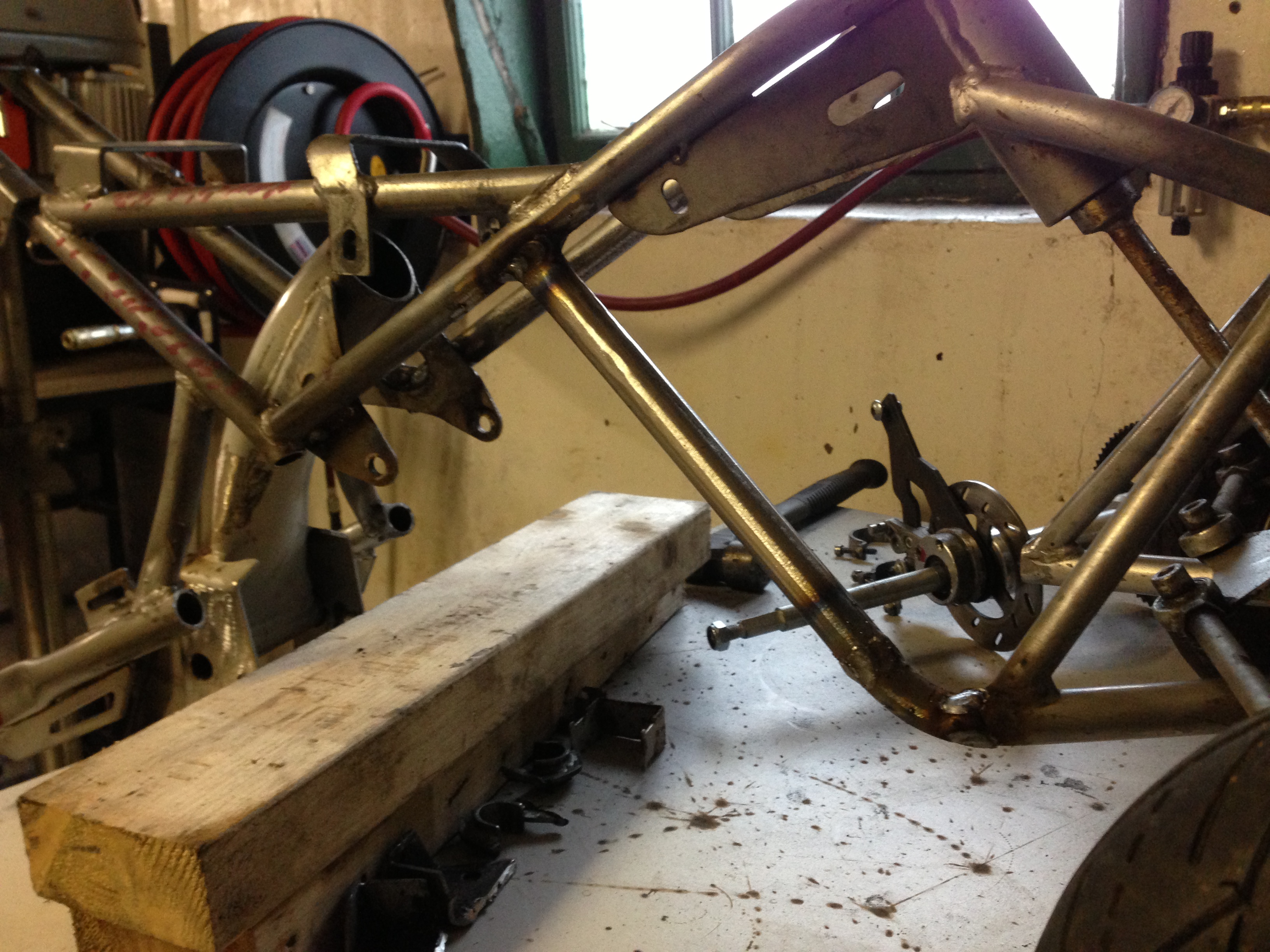
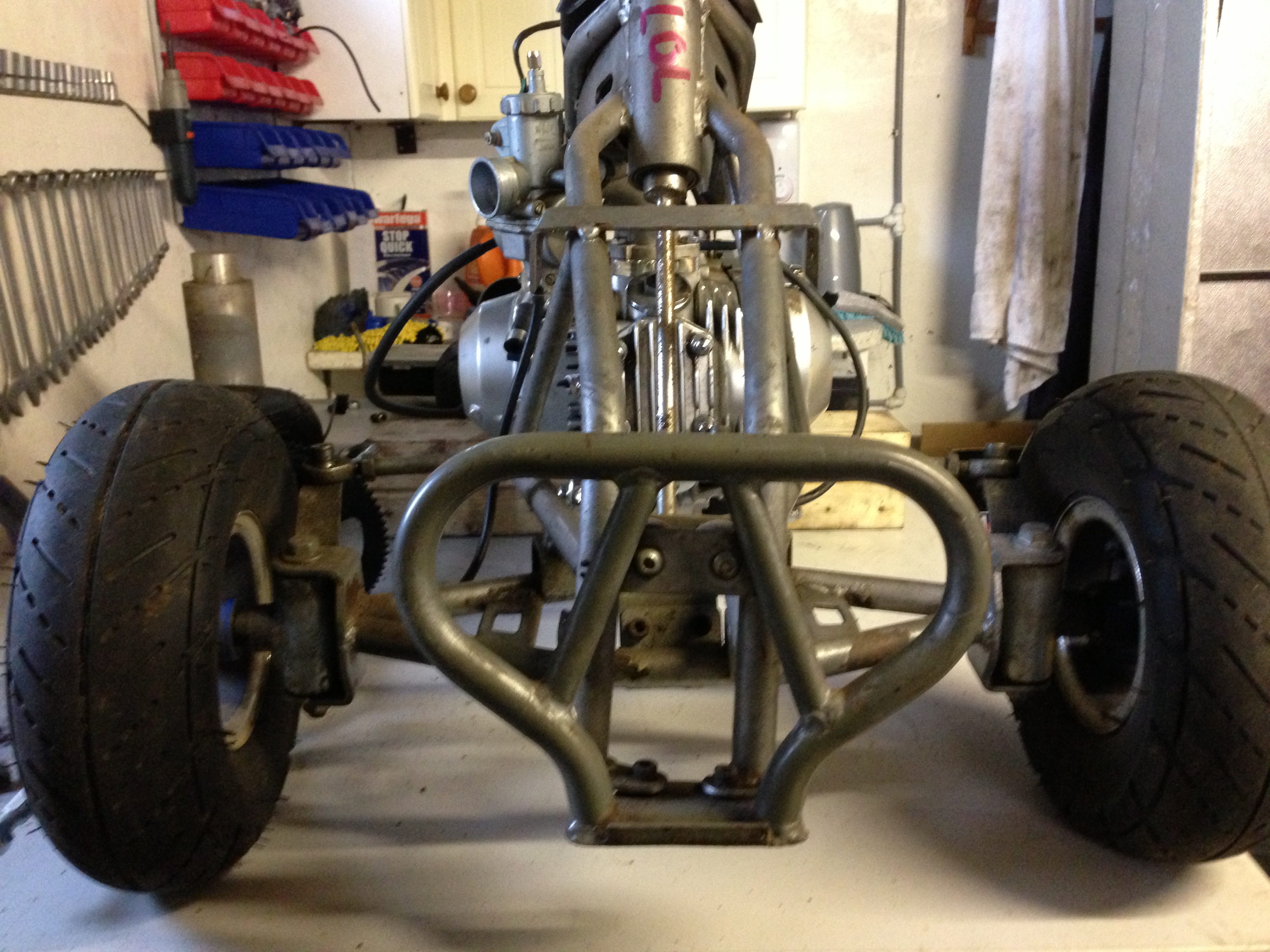
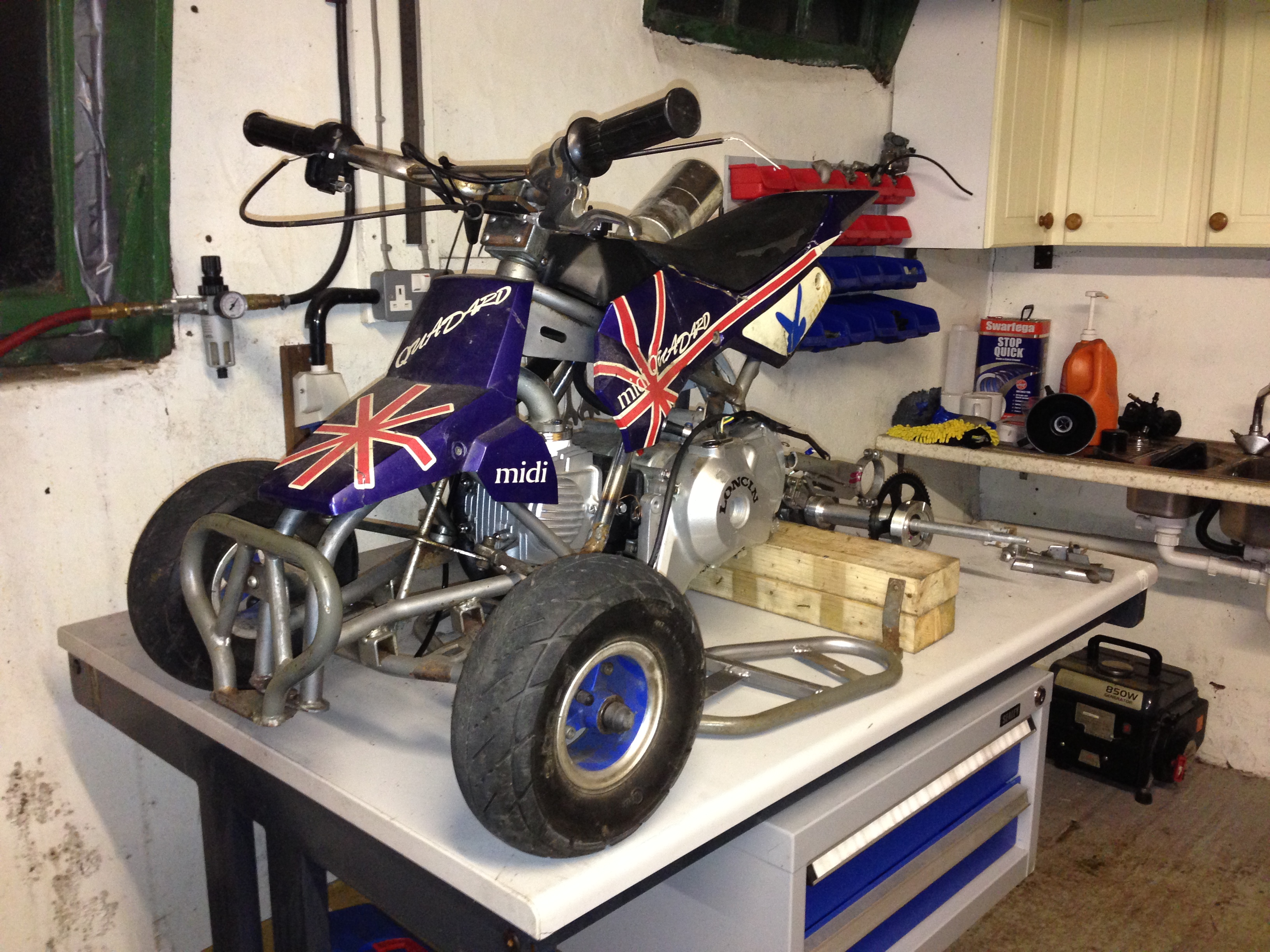
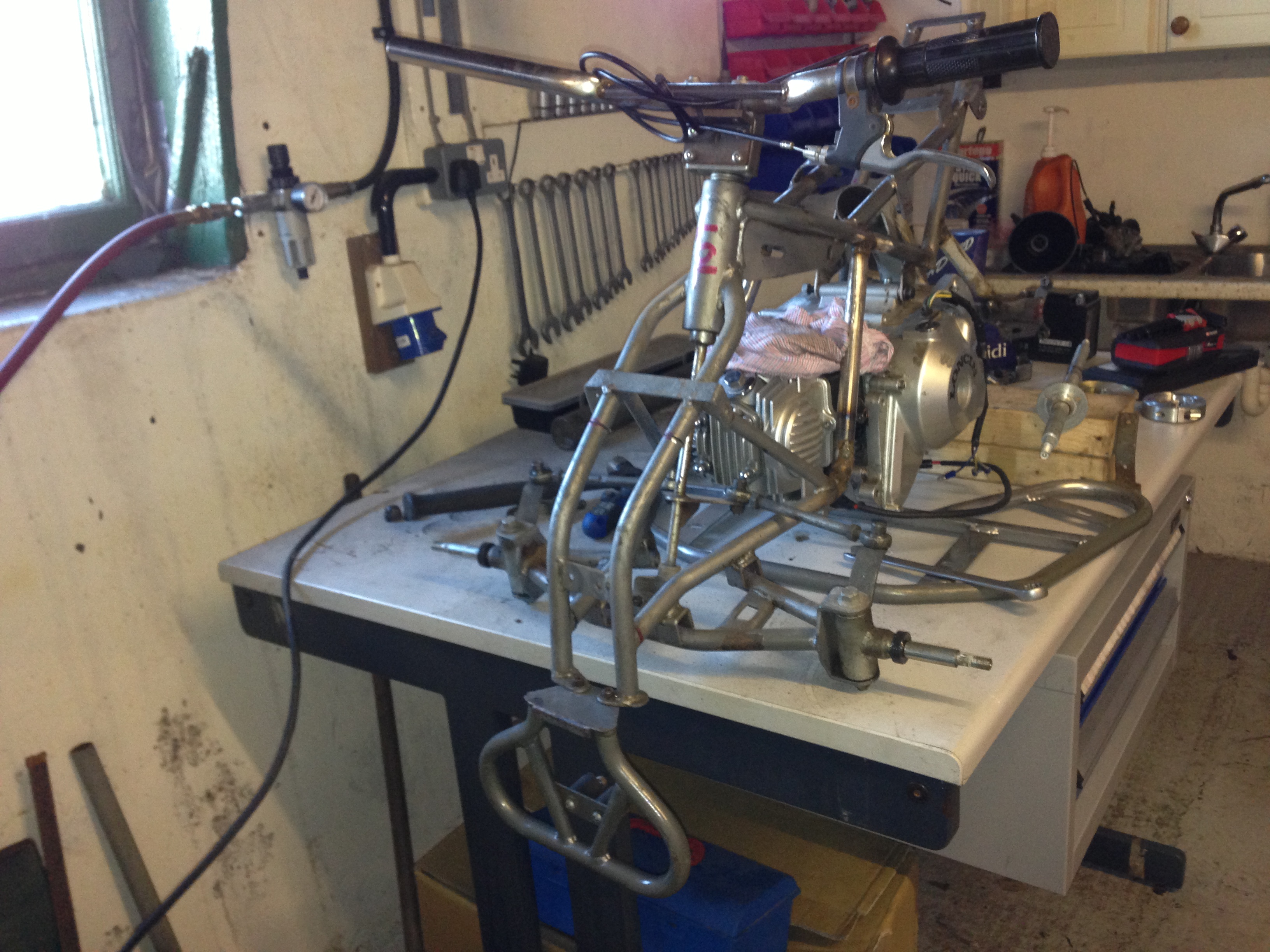
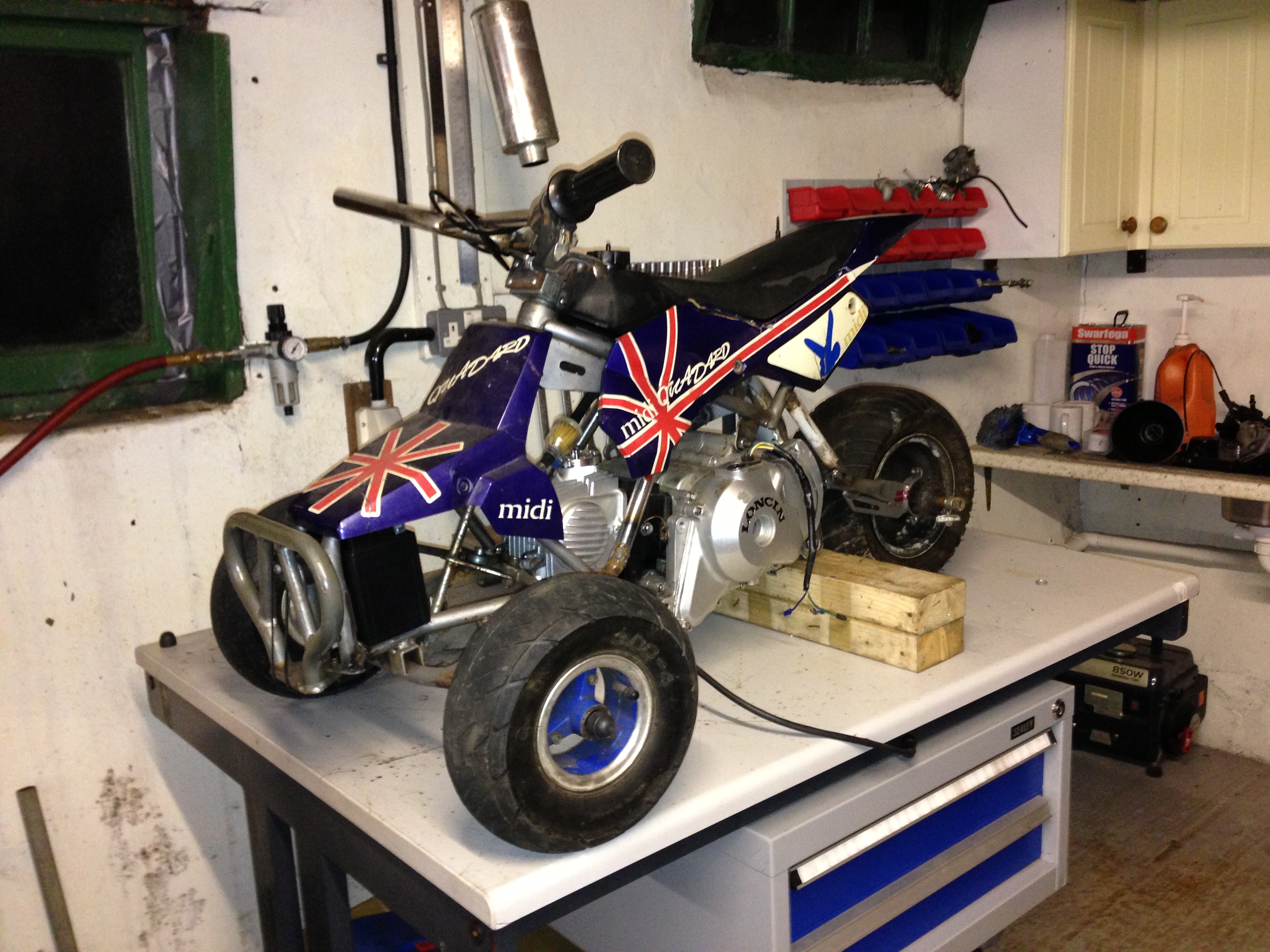
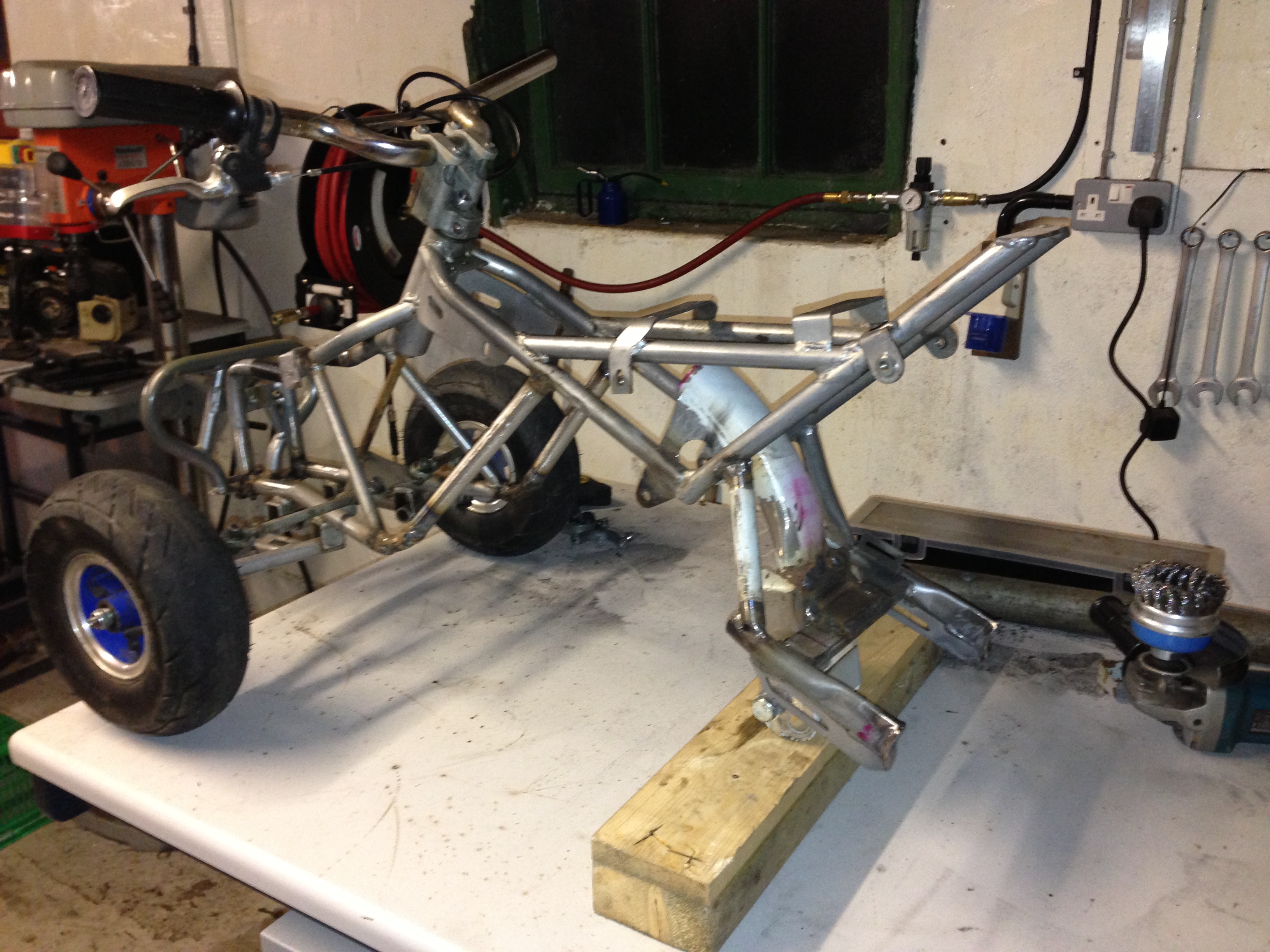
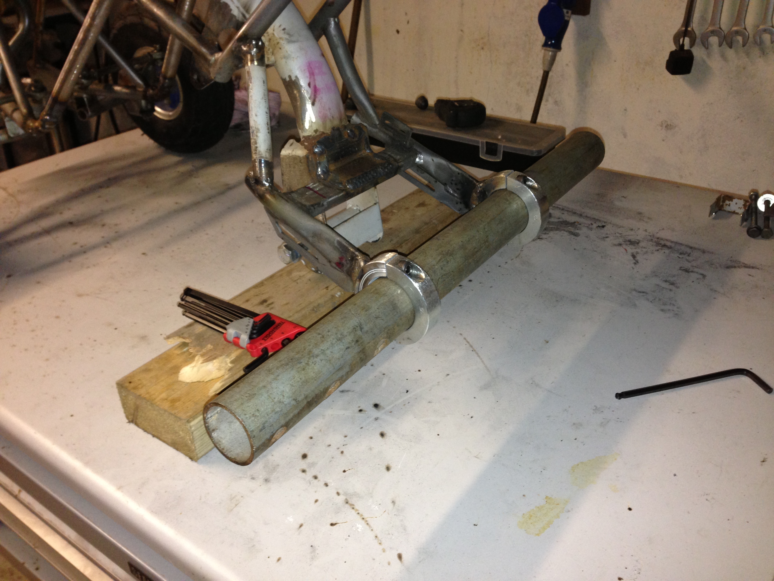
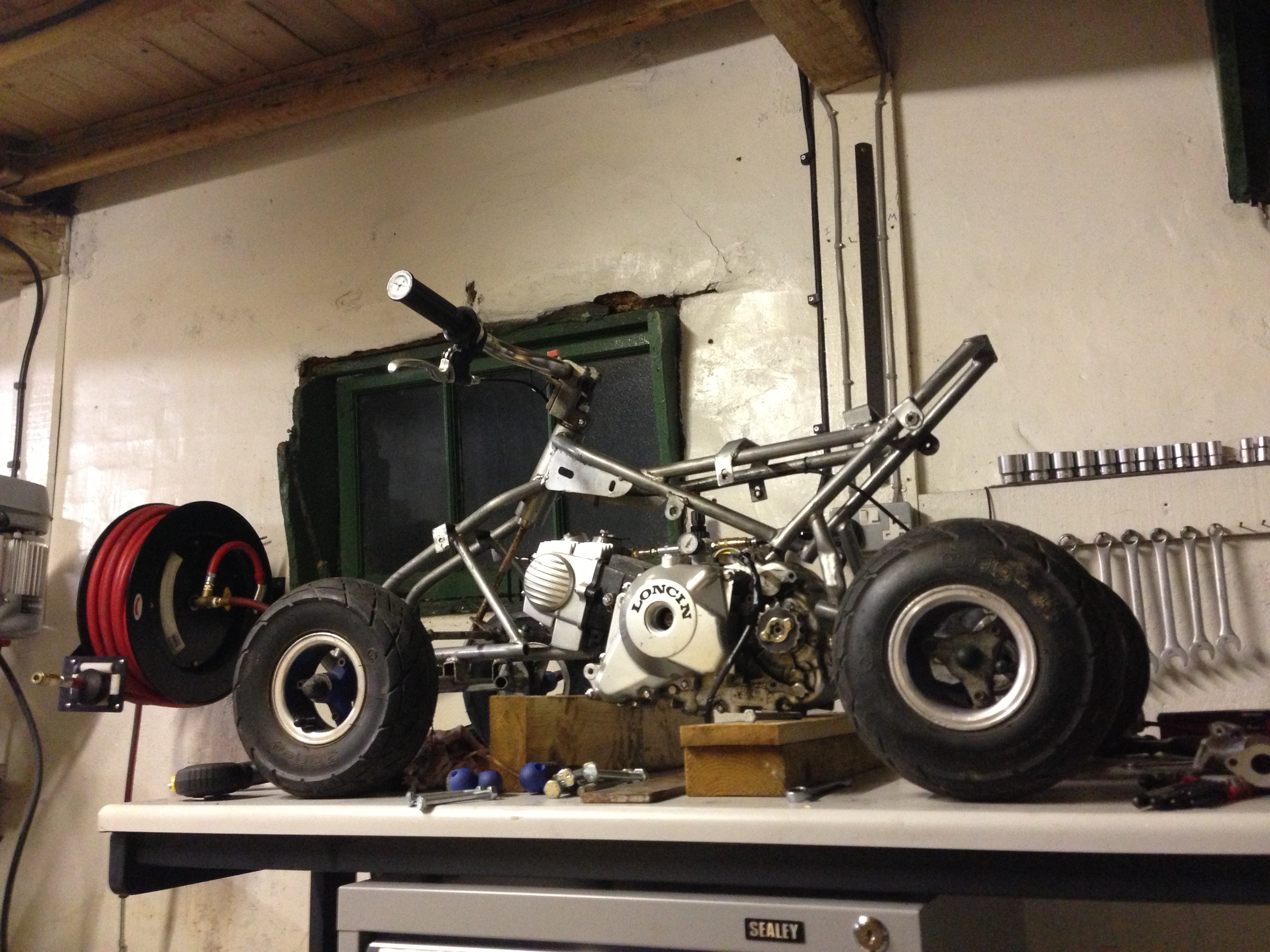
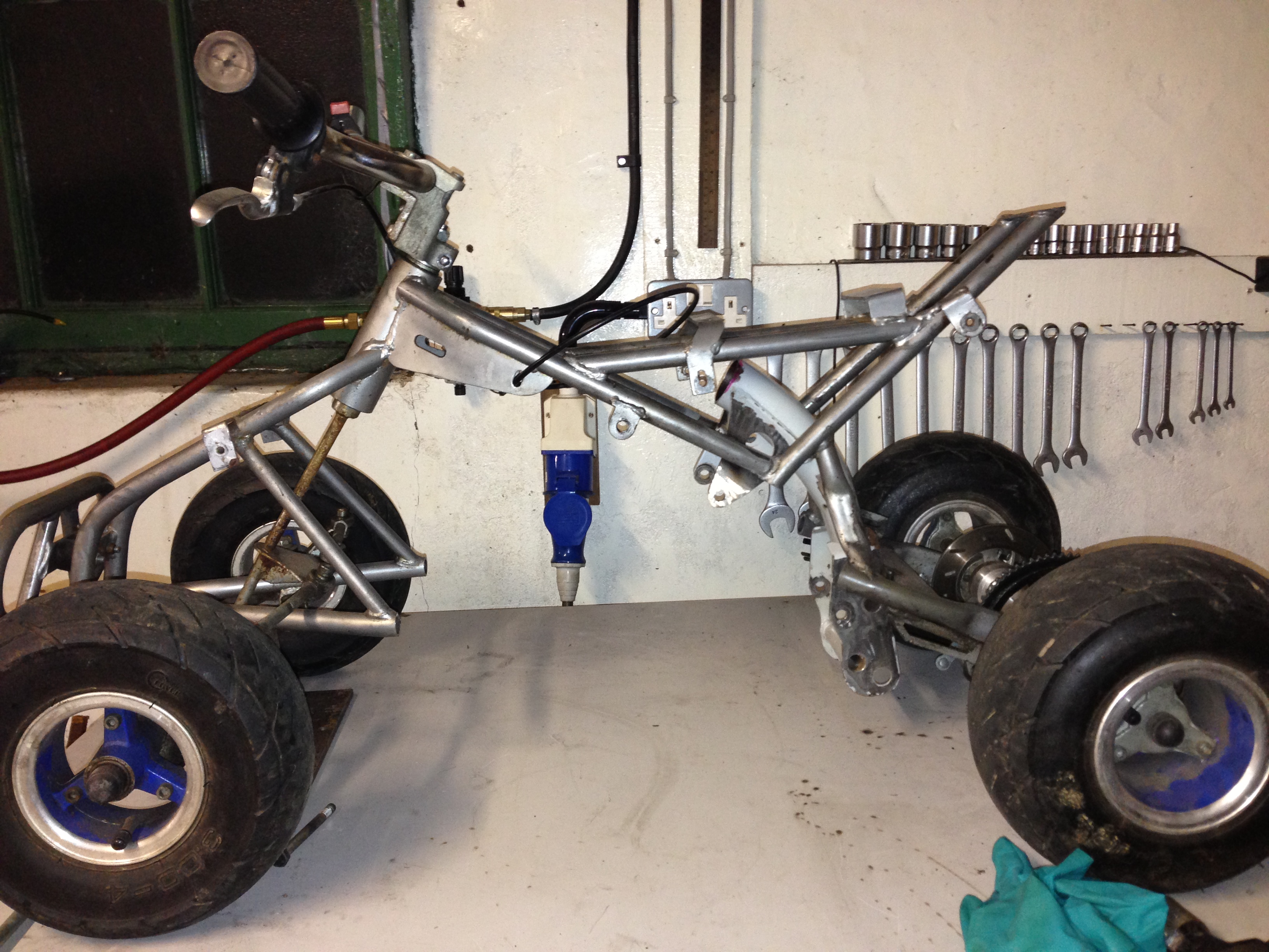
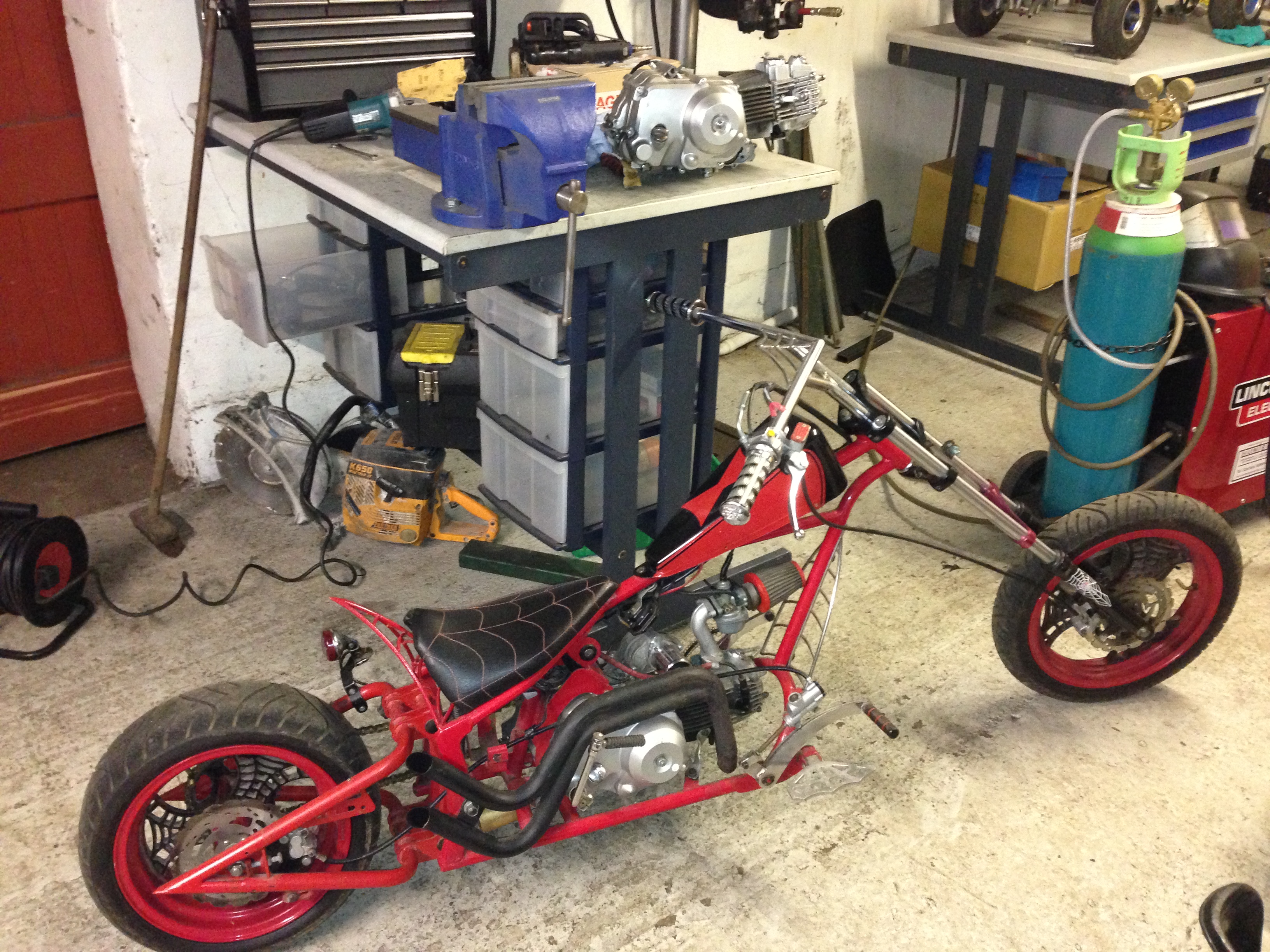
So, I wanted to re-vamp my favourite early blata replica quad with a bit more power and better reliability, heres what I started with yesterday afternoon:
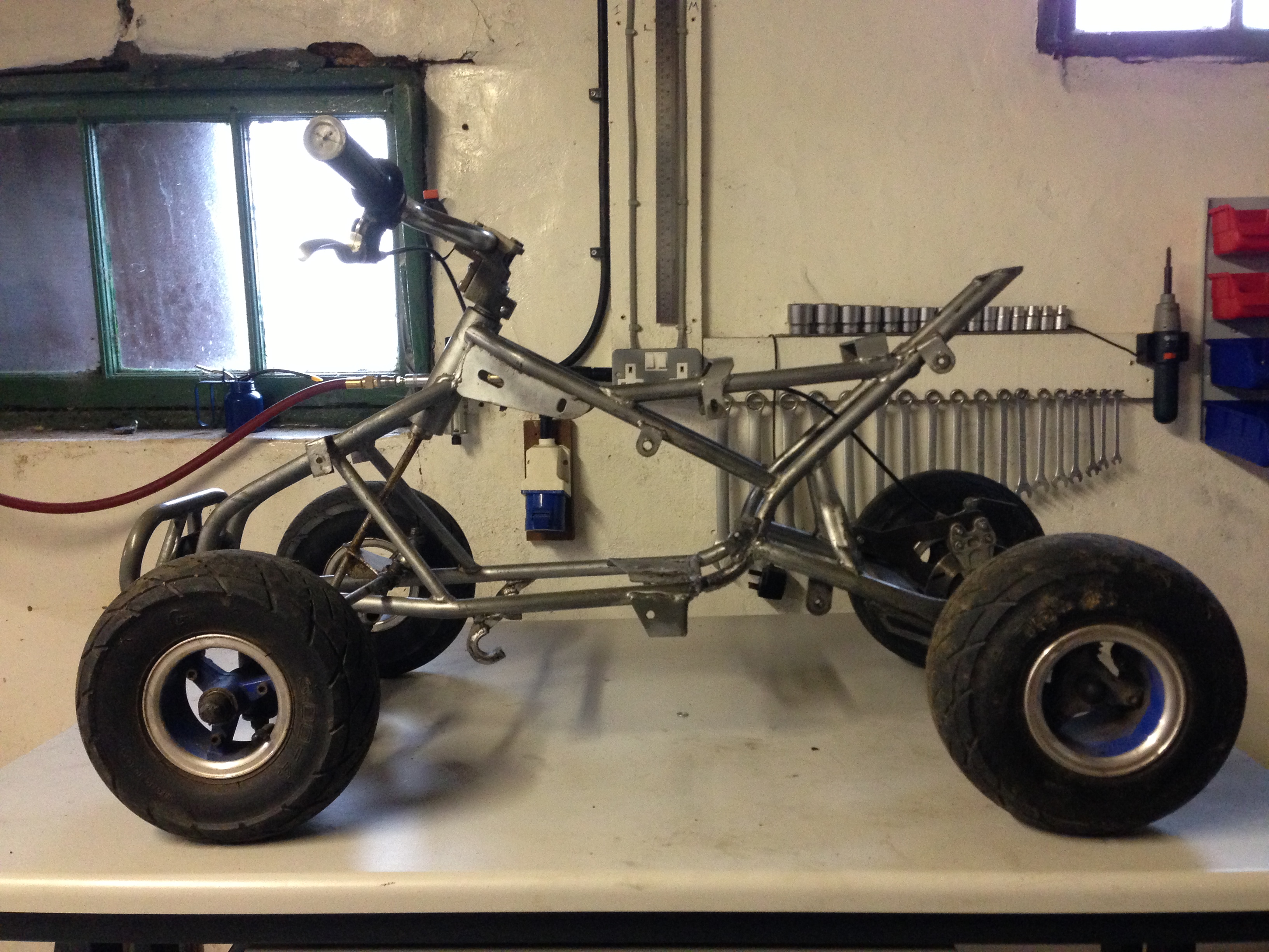
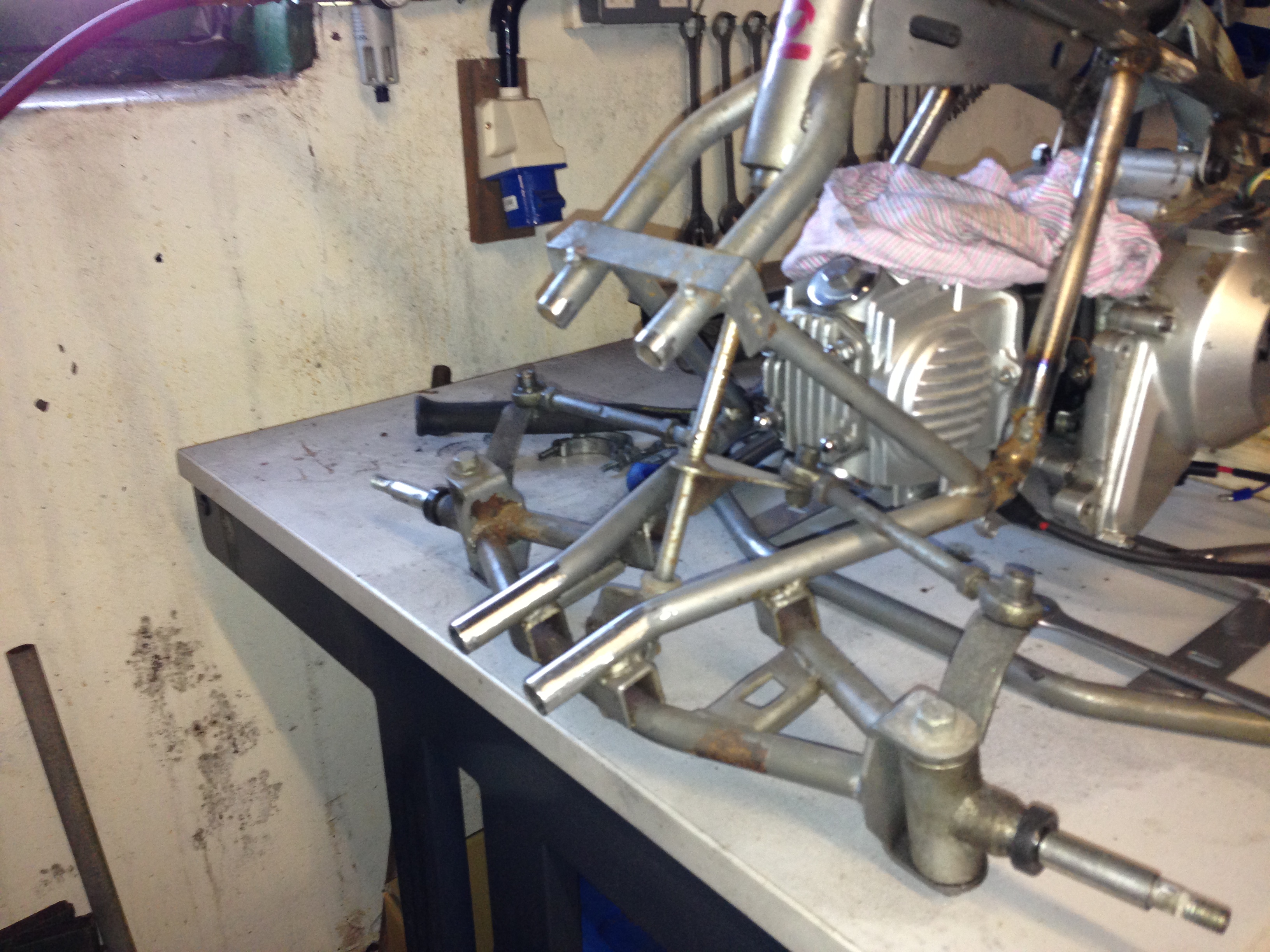
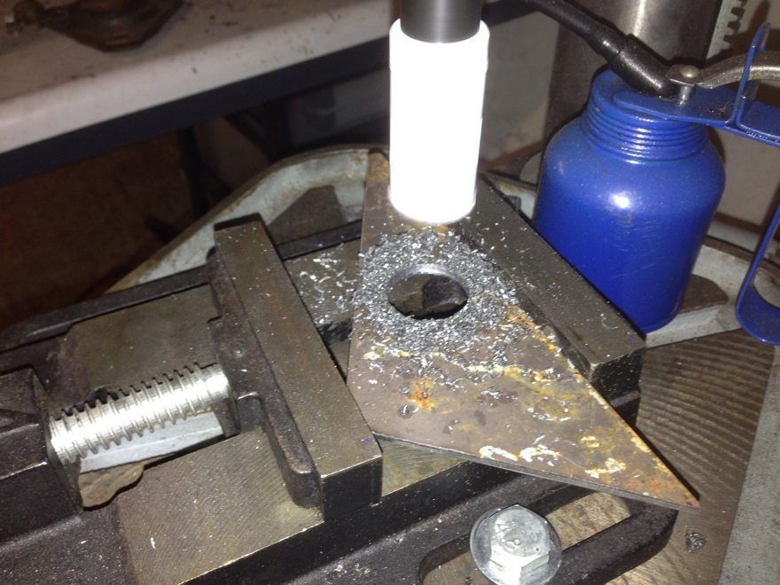
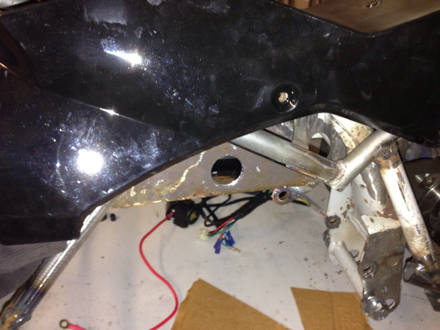
started by cutting the original engine mount plate out and the surrounding steelwork to try to massage the 110cc engine into place:
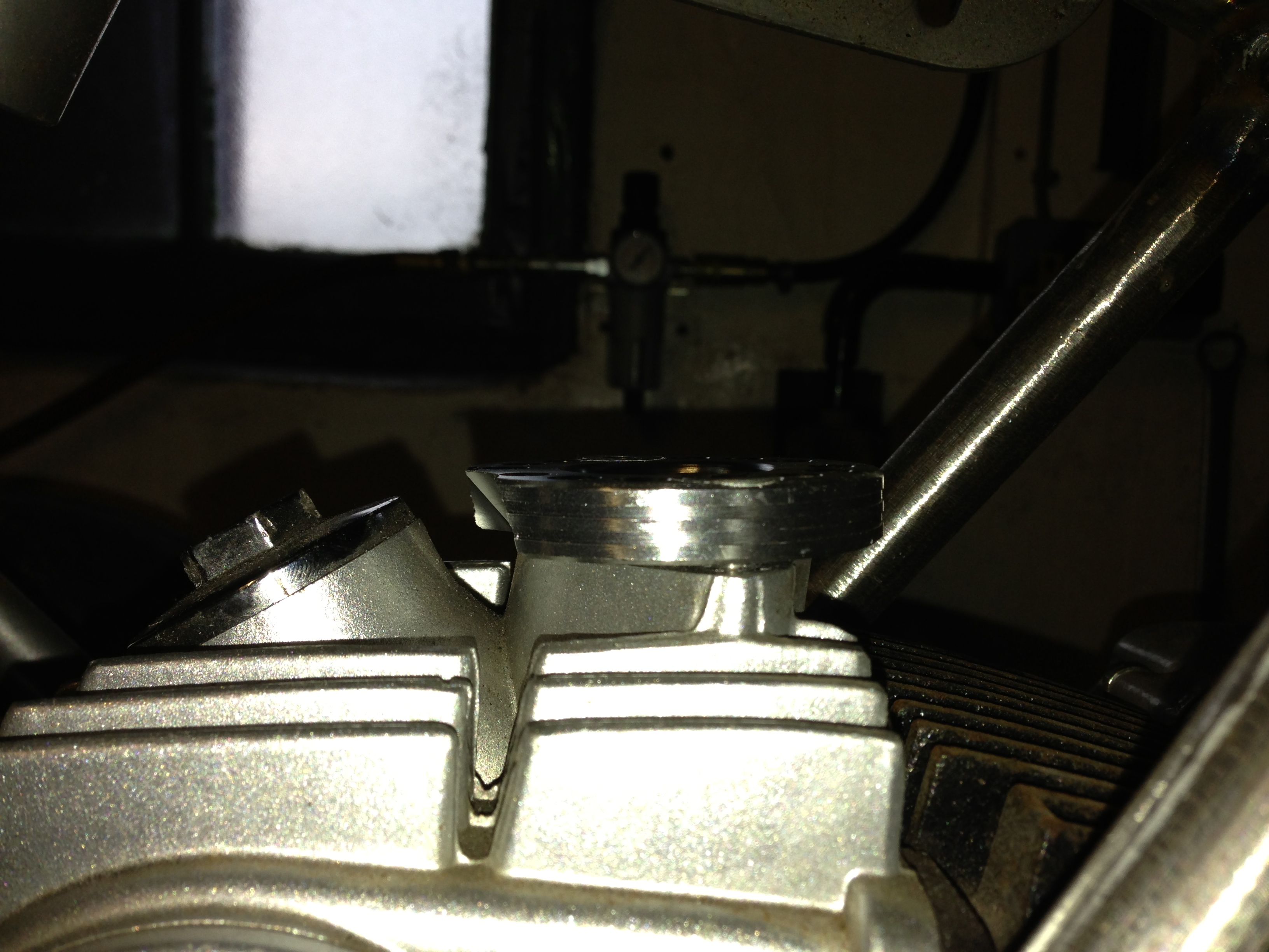
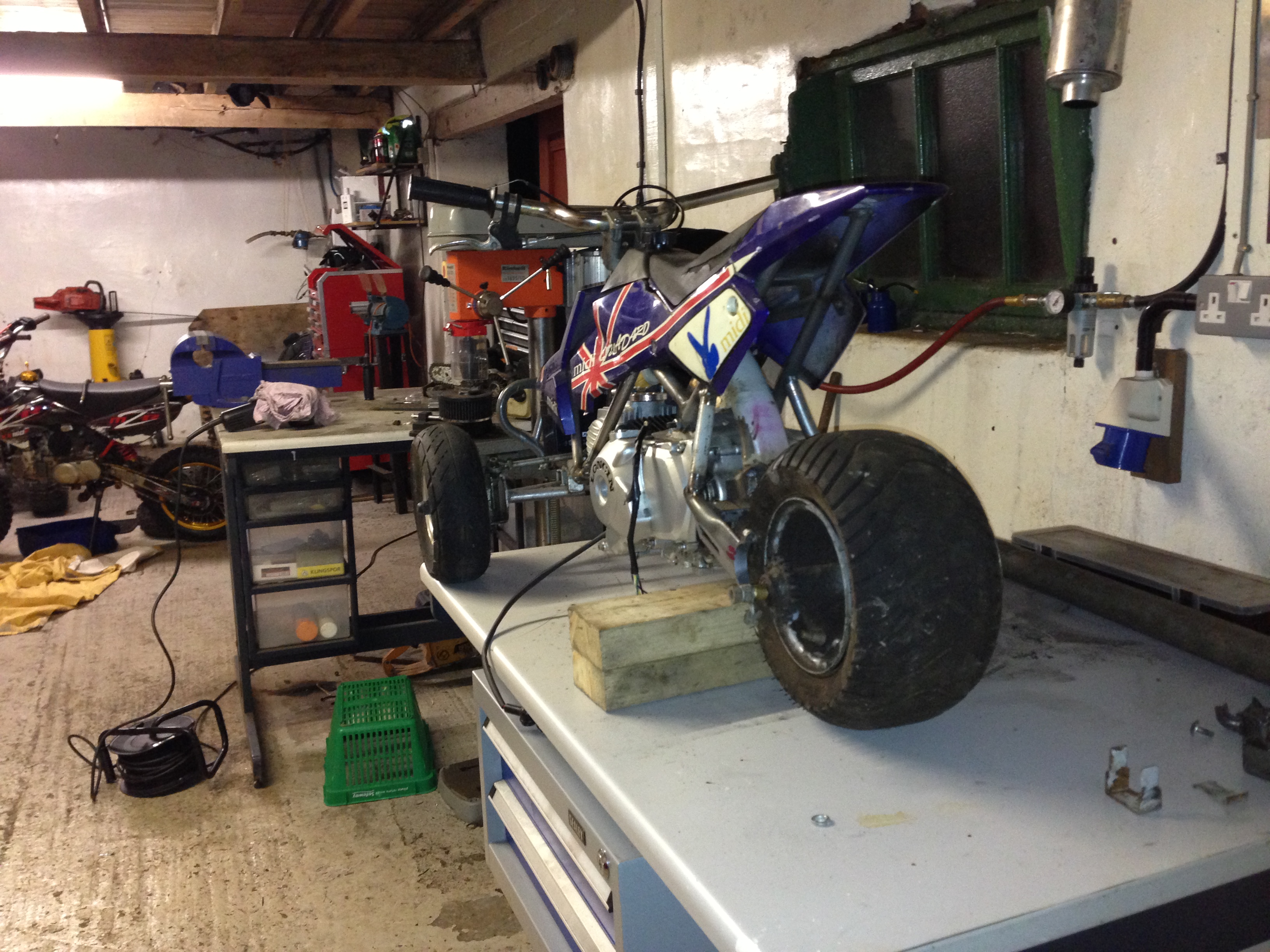
Its tight! But do-able:
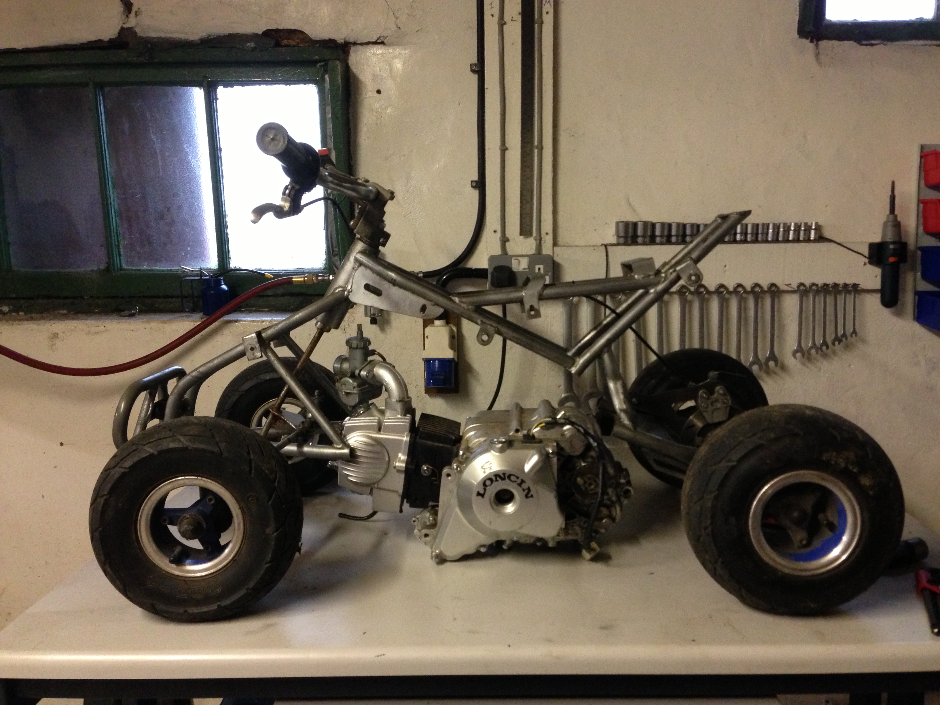
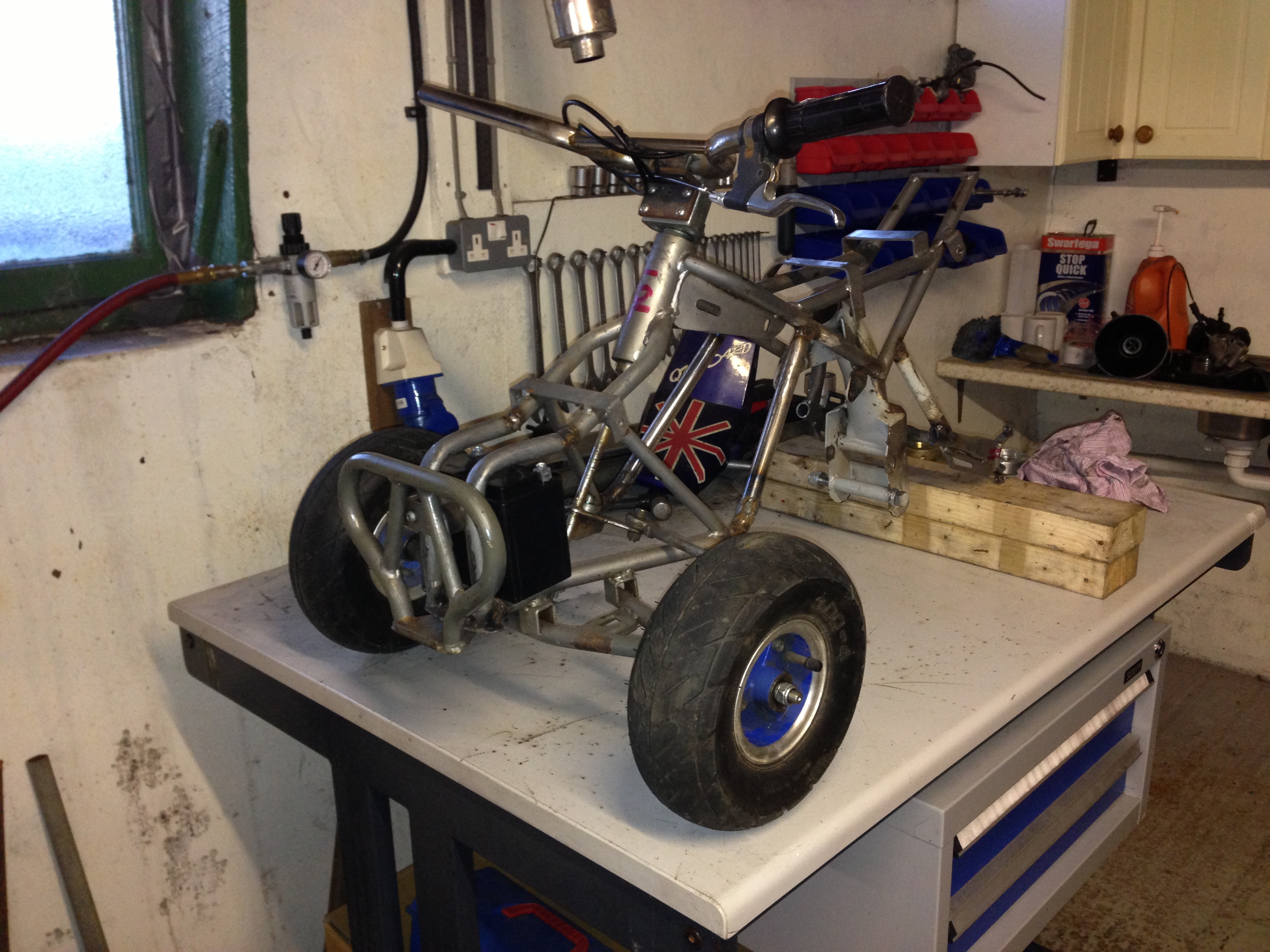
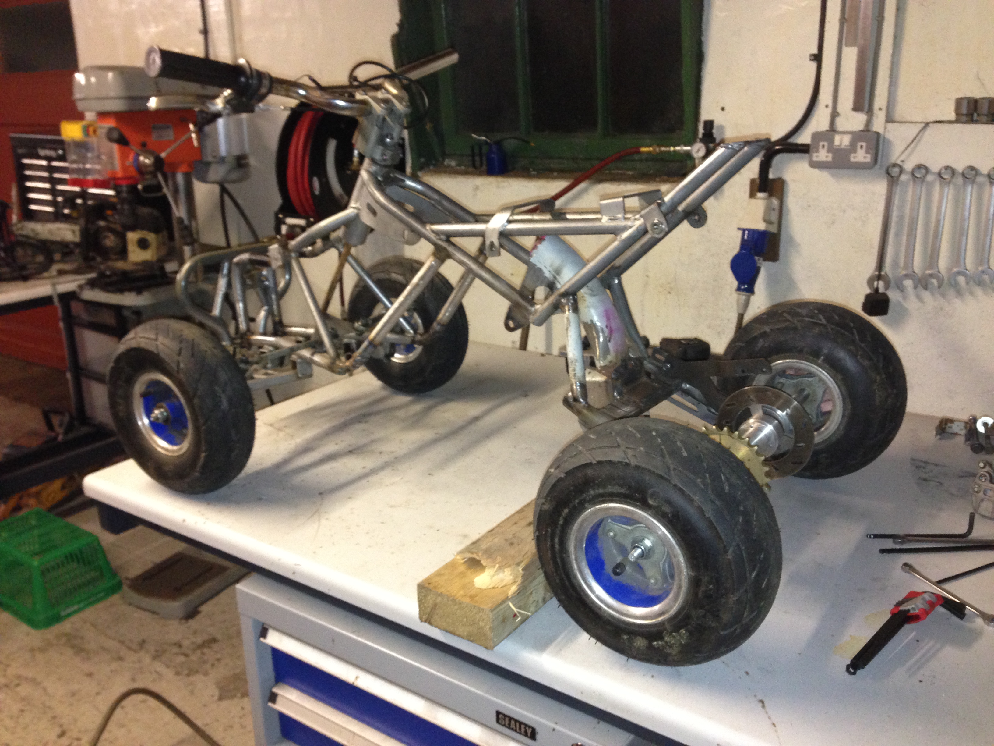
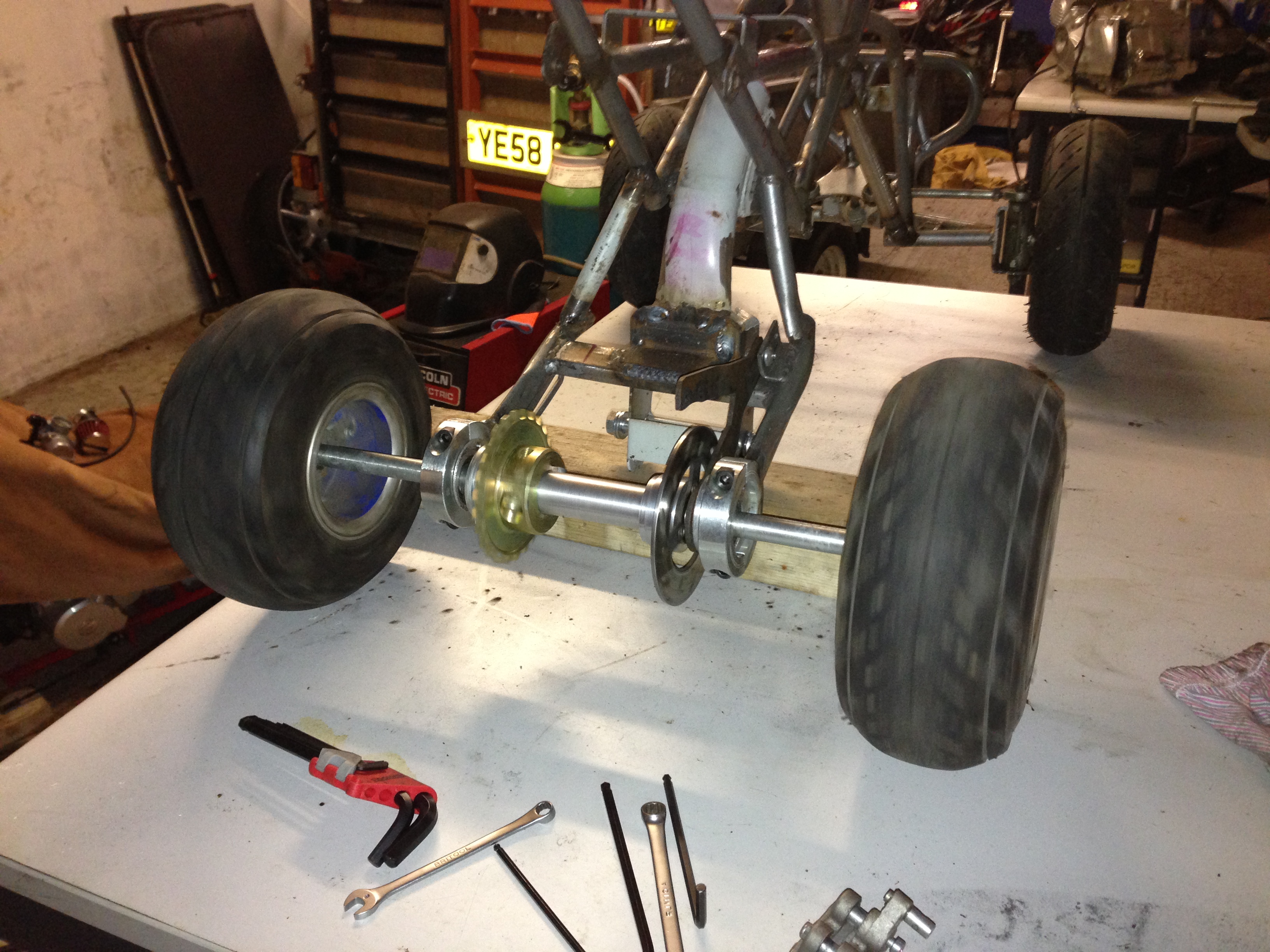
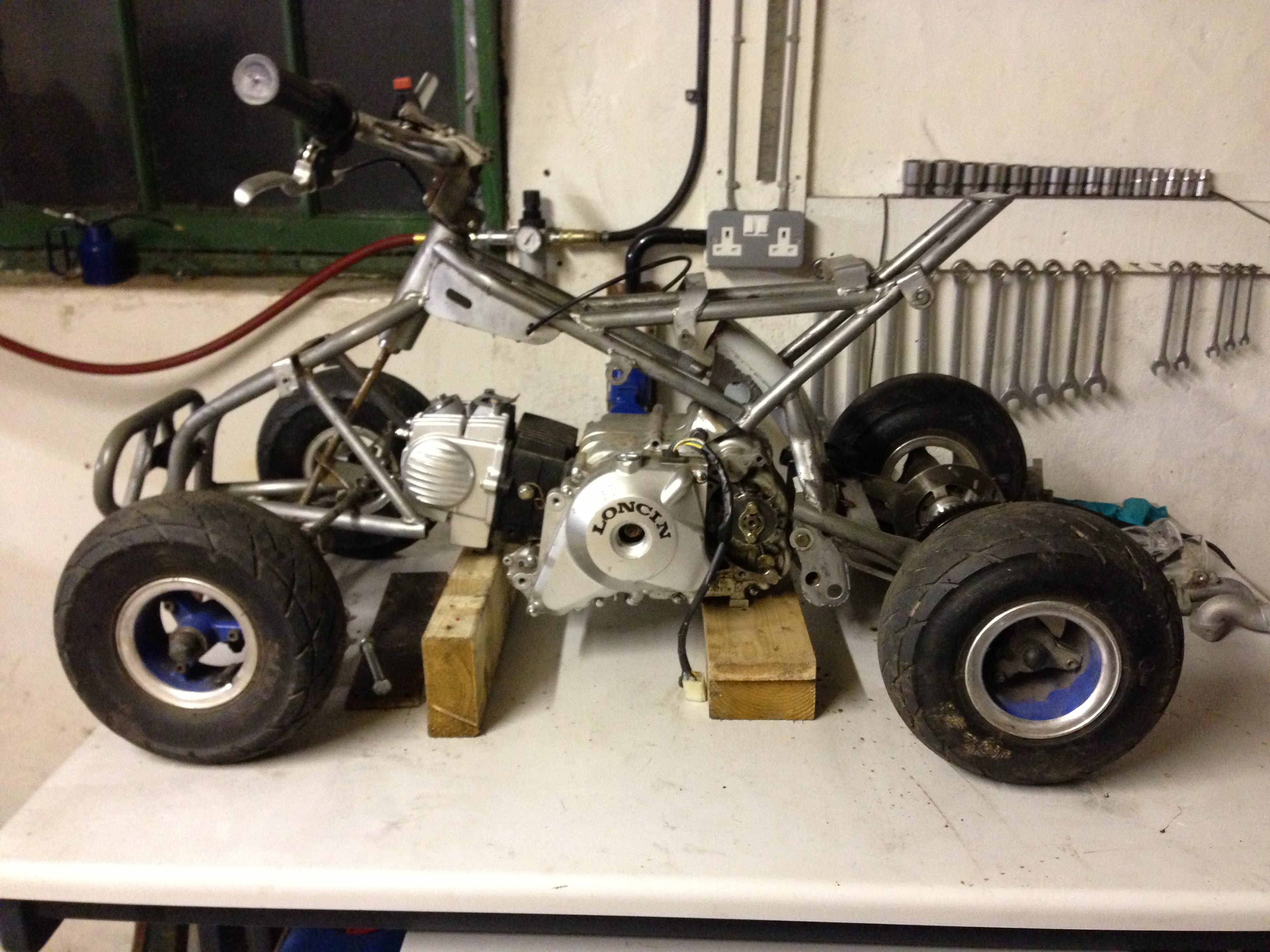
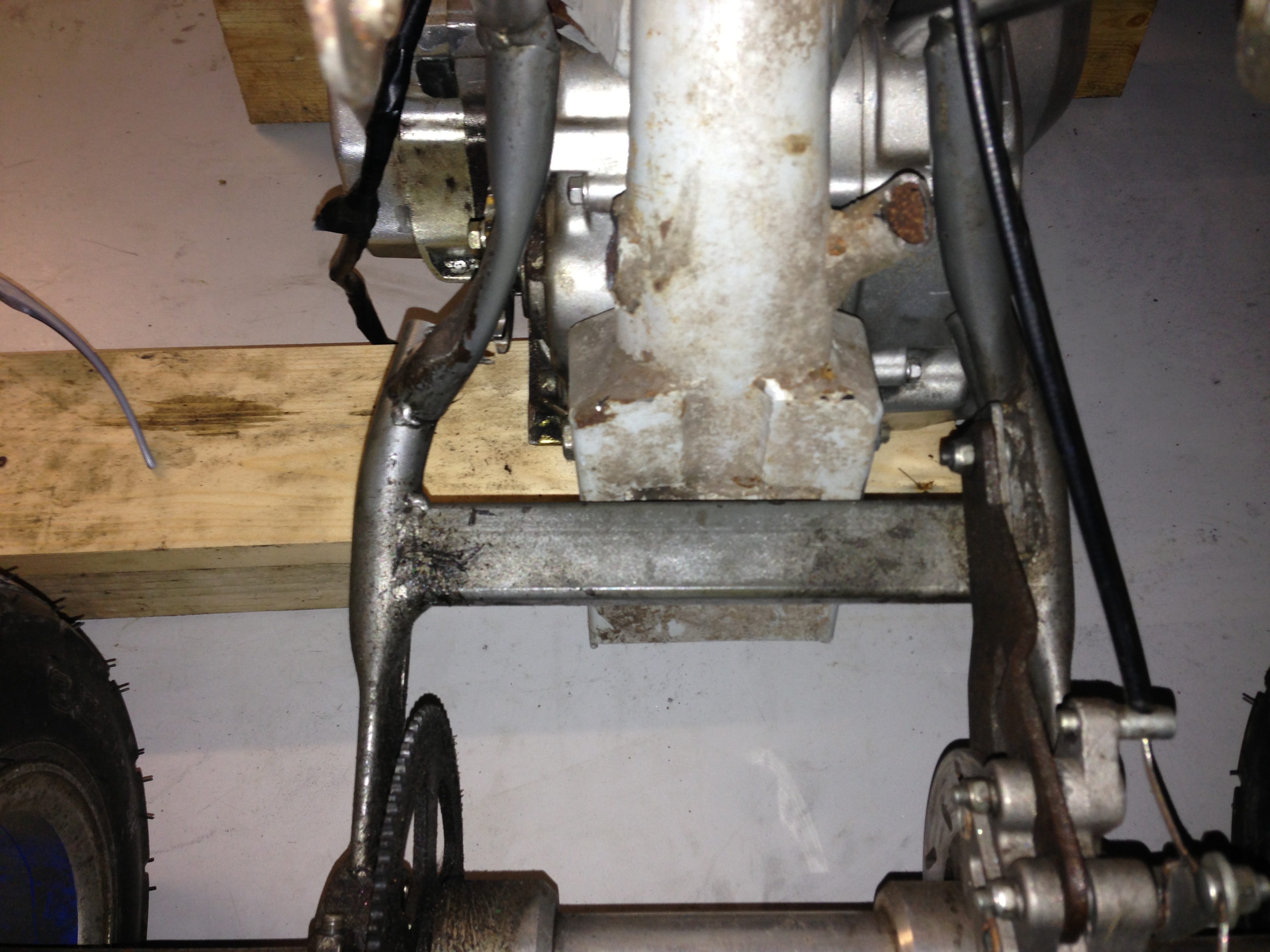
Blocked the engine up into place to give me an Idea of ride Height and how to mount the engine:
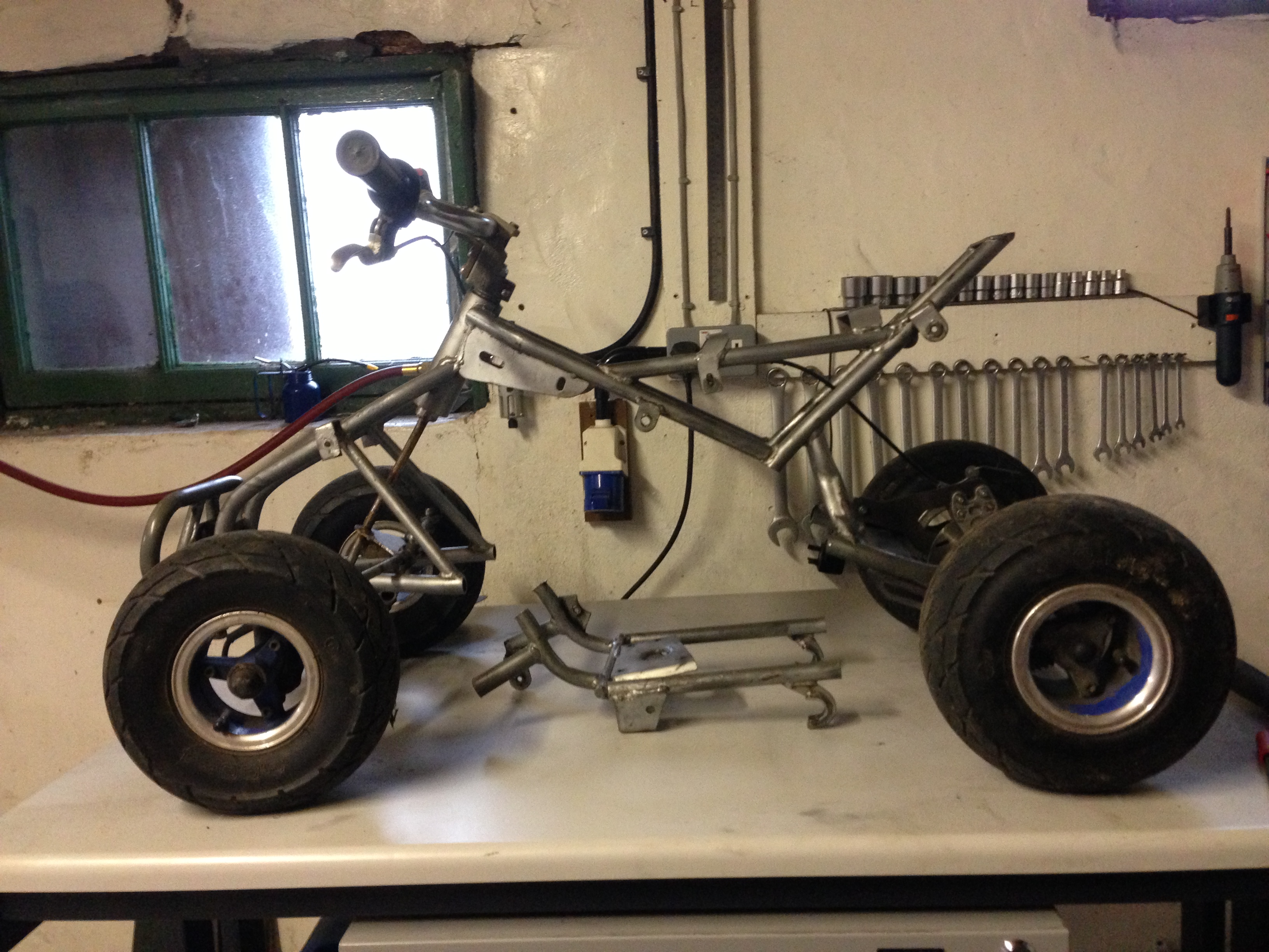
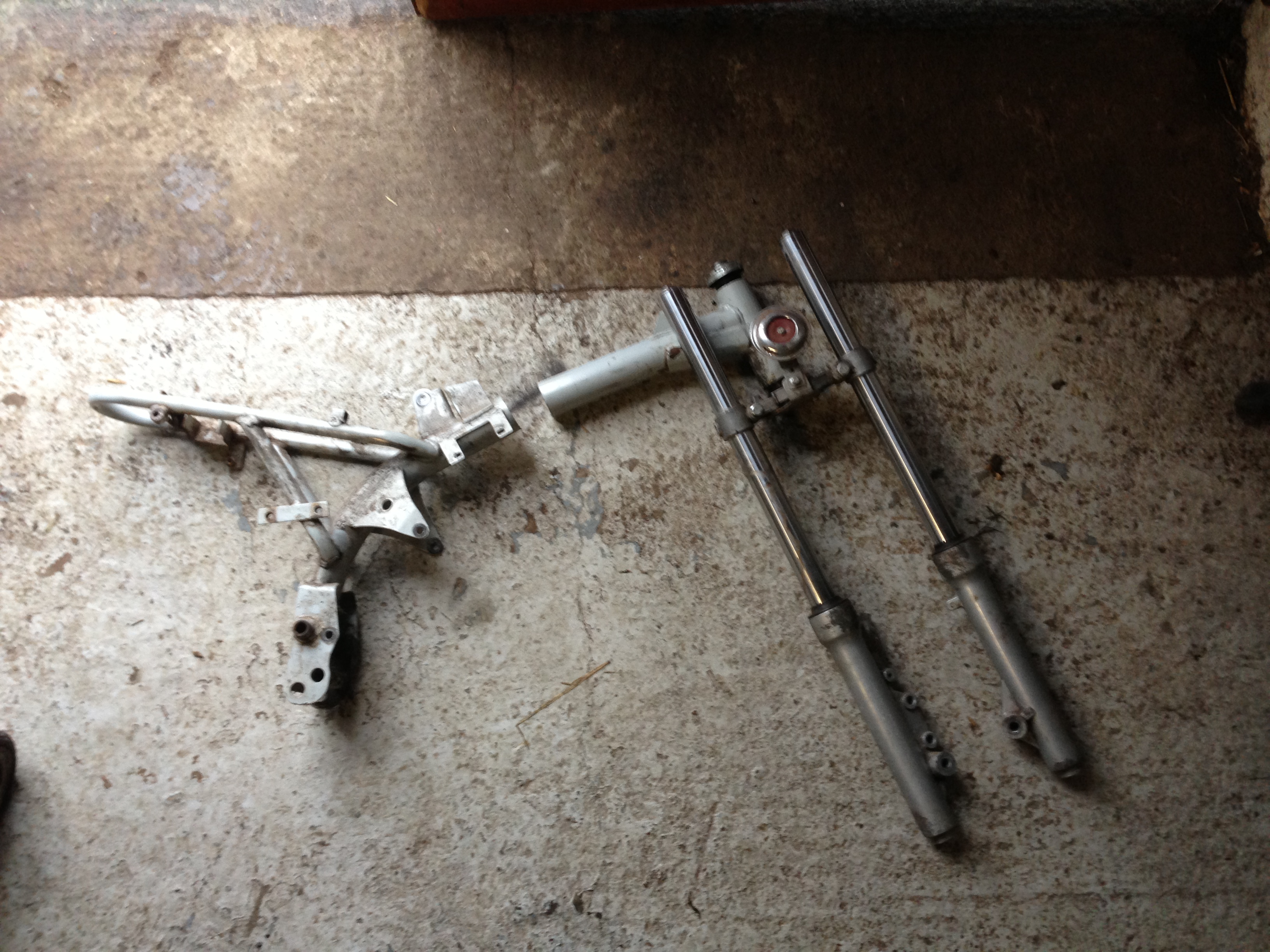
Which led to me realising the easiest way would be to cut up a spare pitbike frame for its mounts:
This isnt going to be a thing of beauty by a long stretch of the imagination, I just want it done asap so I can go out on the ice when it arrives!!!
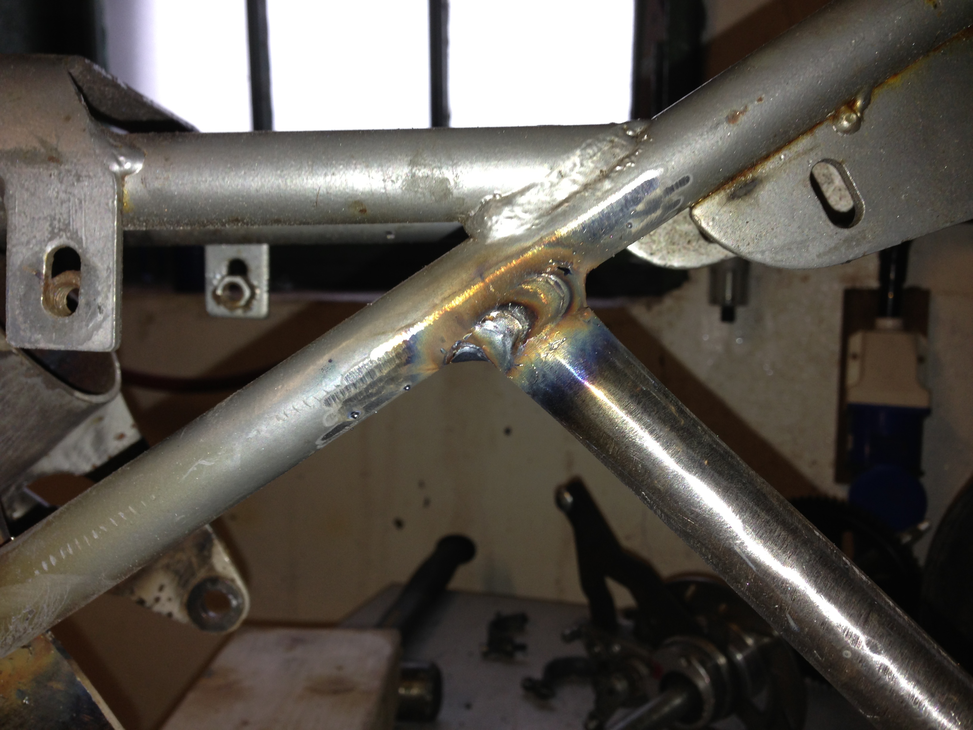
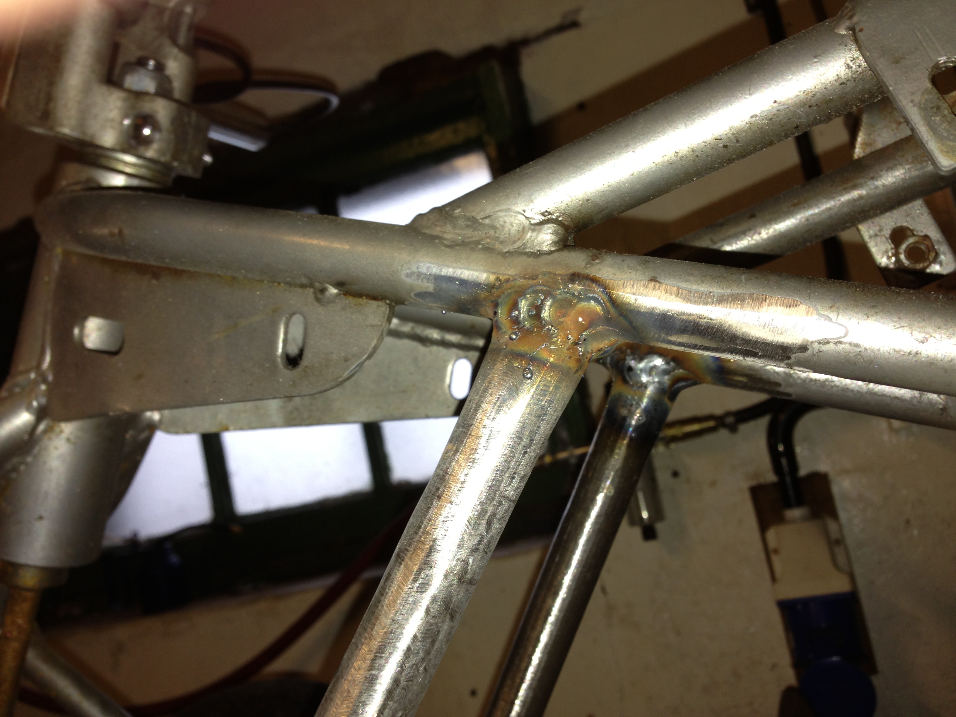
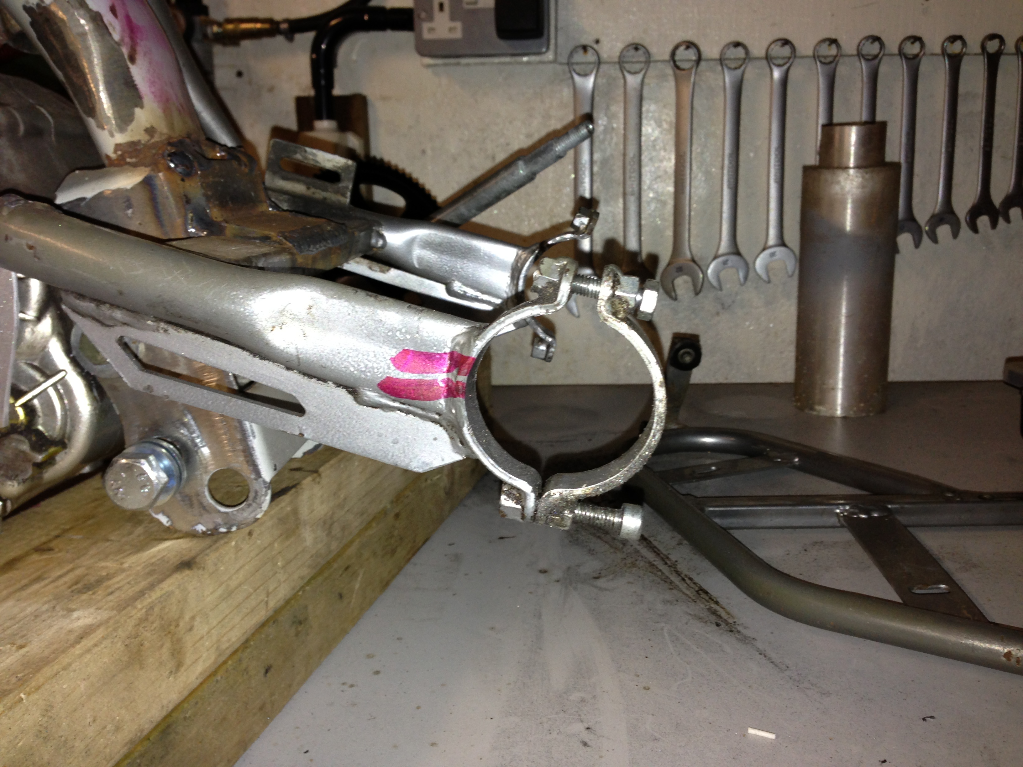
Yesterday/Monday I did some more work on the quad, I started by shaping the backbone piece I cut from the spare frame:
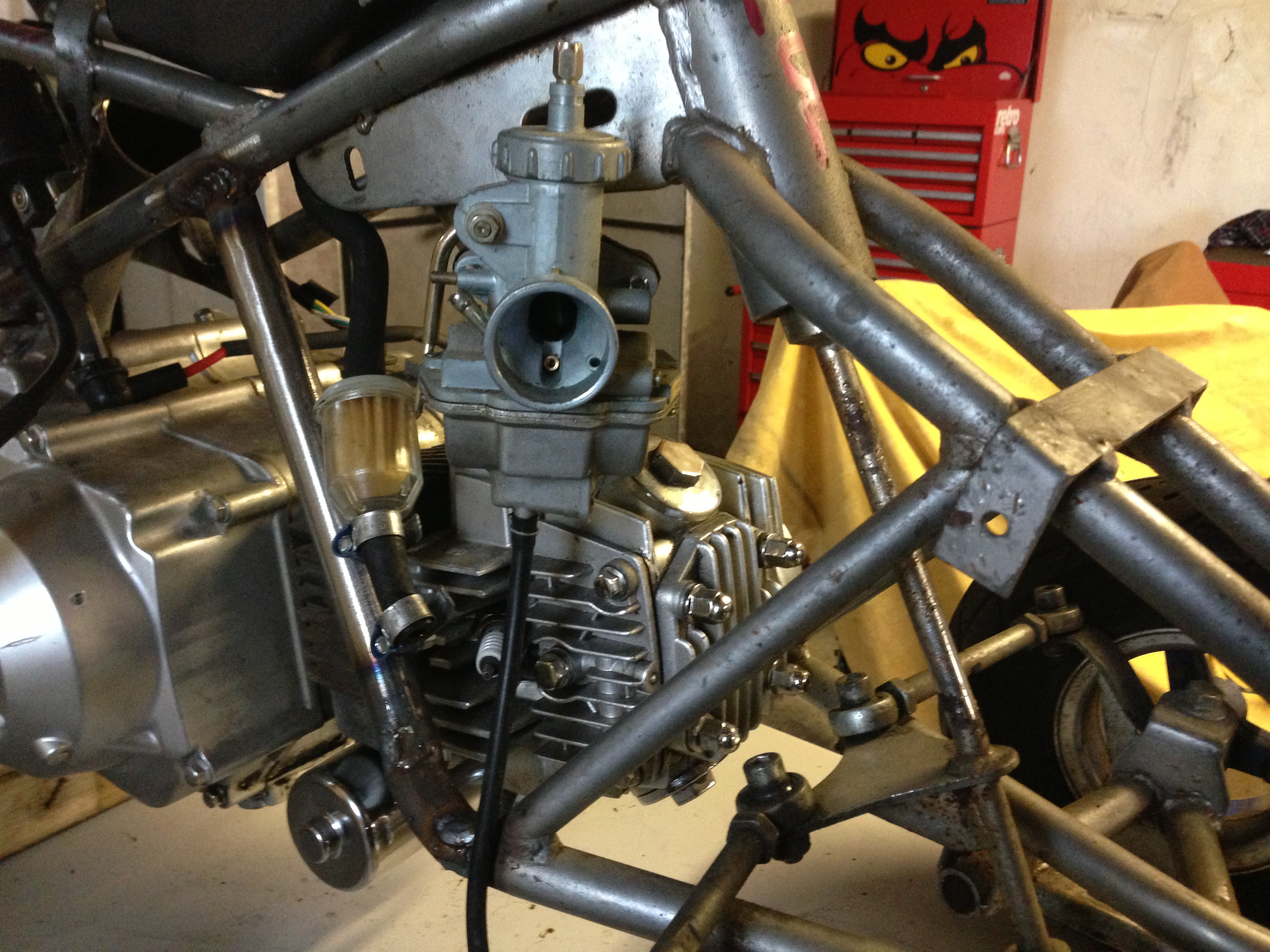
I had mitred and shaped the top of the backbone to match the angle the seat mounting flats ran at but I ended up just chopping that away as I dropped the engine a little further to gain more clearance for the carb.
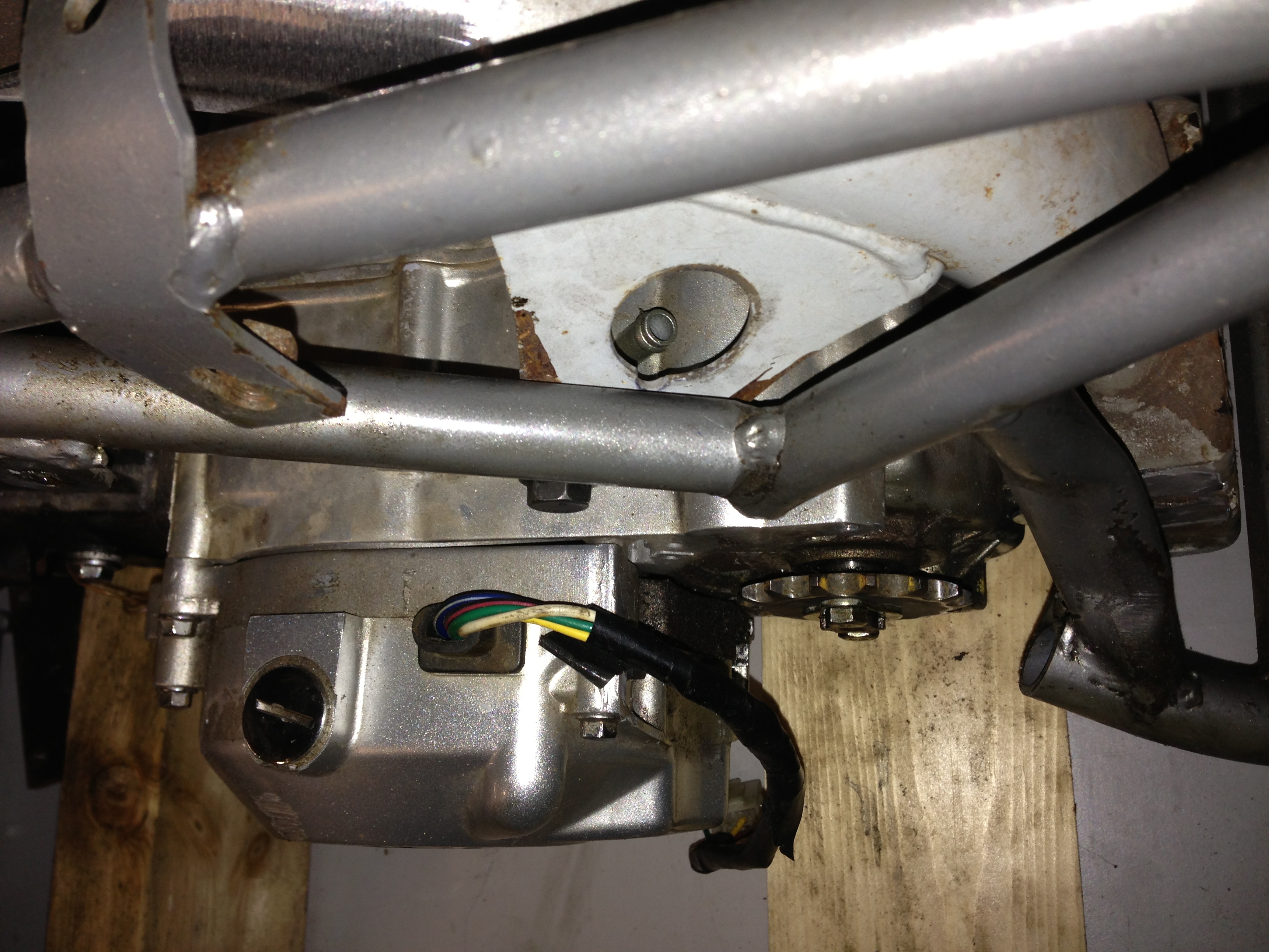
I sat the engine back in place and marked areas that would intersect frame positions where I could tack the backbone into place:
The very back of the original back-bone happened to sit parallel to this rectangular section:
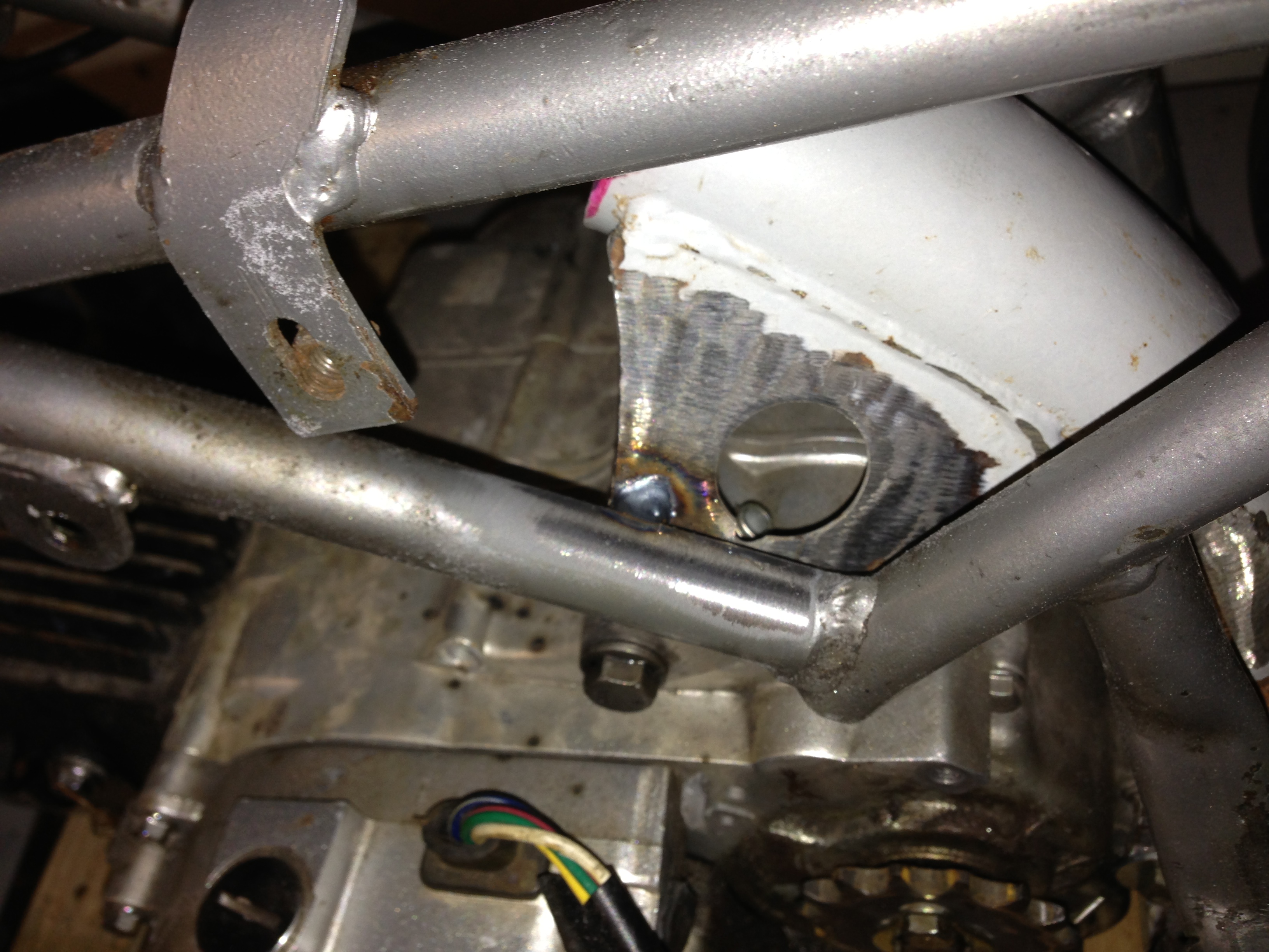
and the two brackets that came off the backbone for the top engine mount touched the insides of the quad frame:
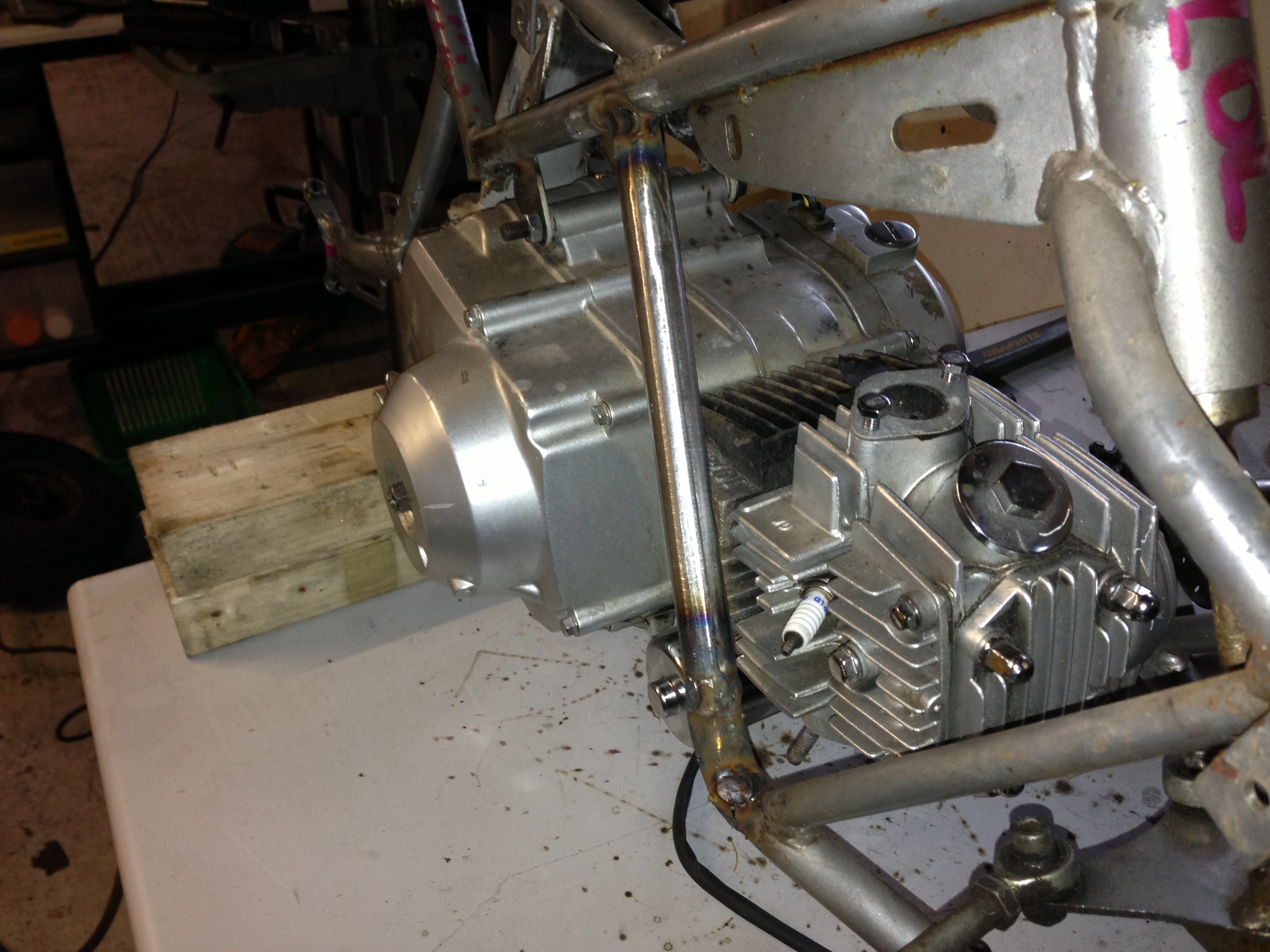
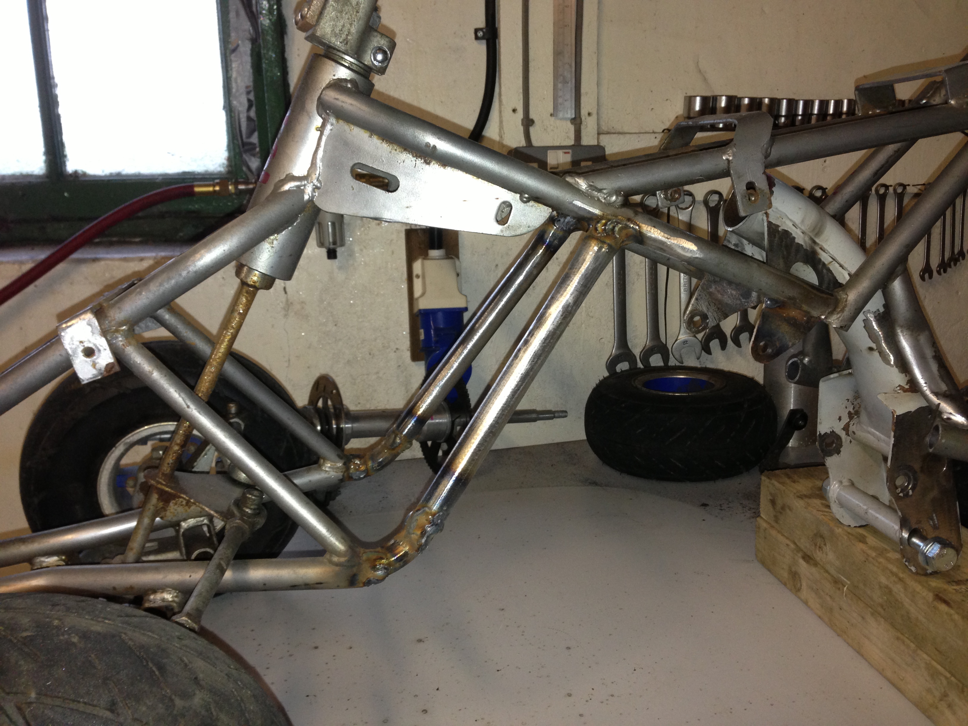
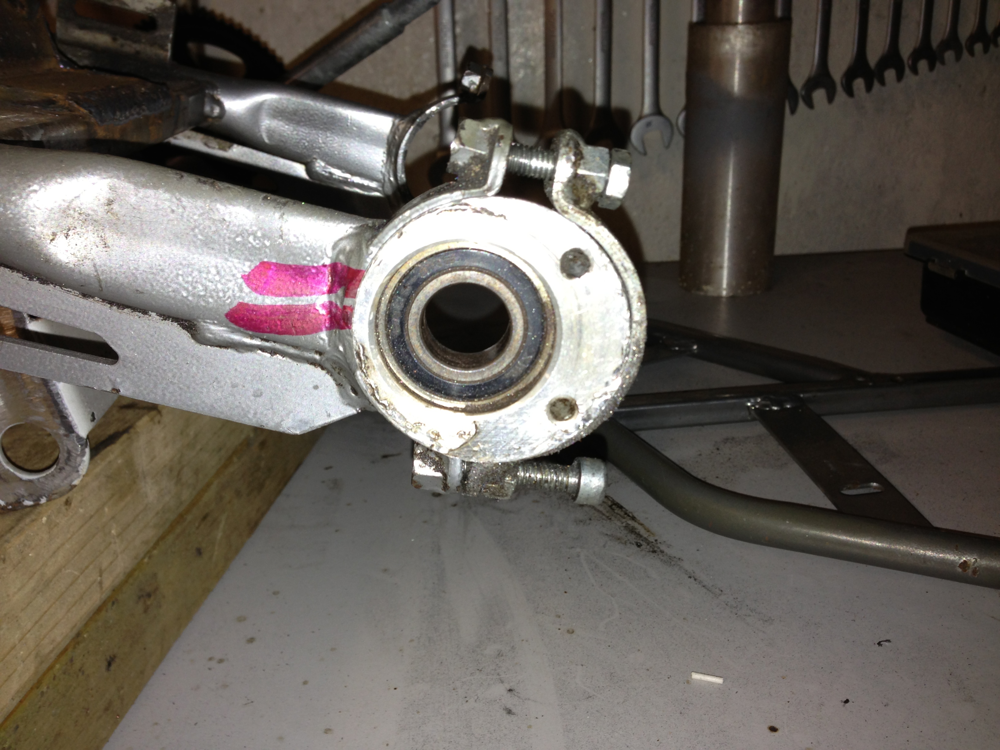
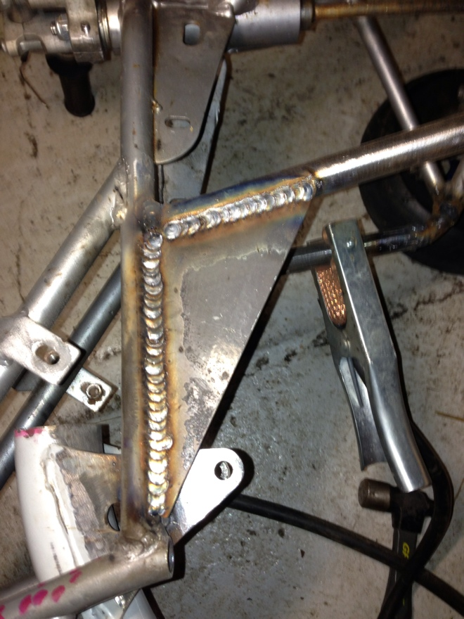
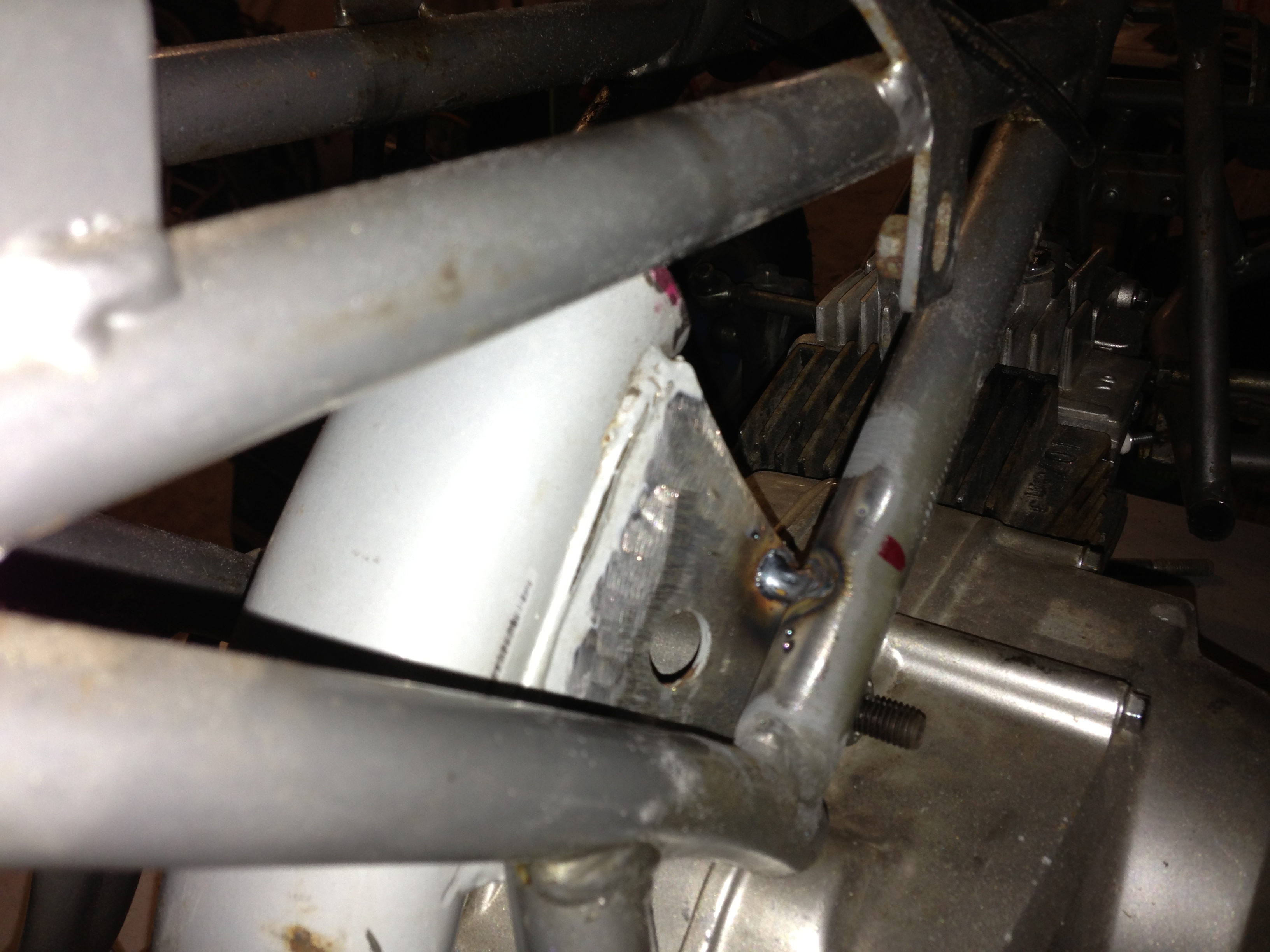
After that, I took the engine and backbone back out to clean up the areas I'd weld to on the frame and the backbone. At the same time I took the opportunity to neaten up the backbone a little of all the original pieces that were on it that I wasn't going to use and wouldnt have access to cut off after. weight saving ftw lol. I was hoping to not have to remove the rear swing-arm assembly but in order to fully prep the area I had to ( no pics ). After that, I just put the engine back in place, and tack welded the back-bone in.
Left side:
Right Side:
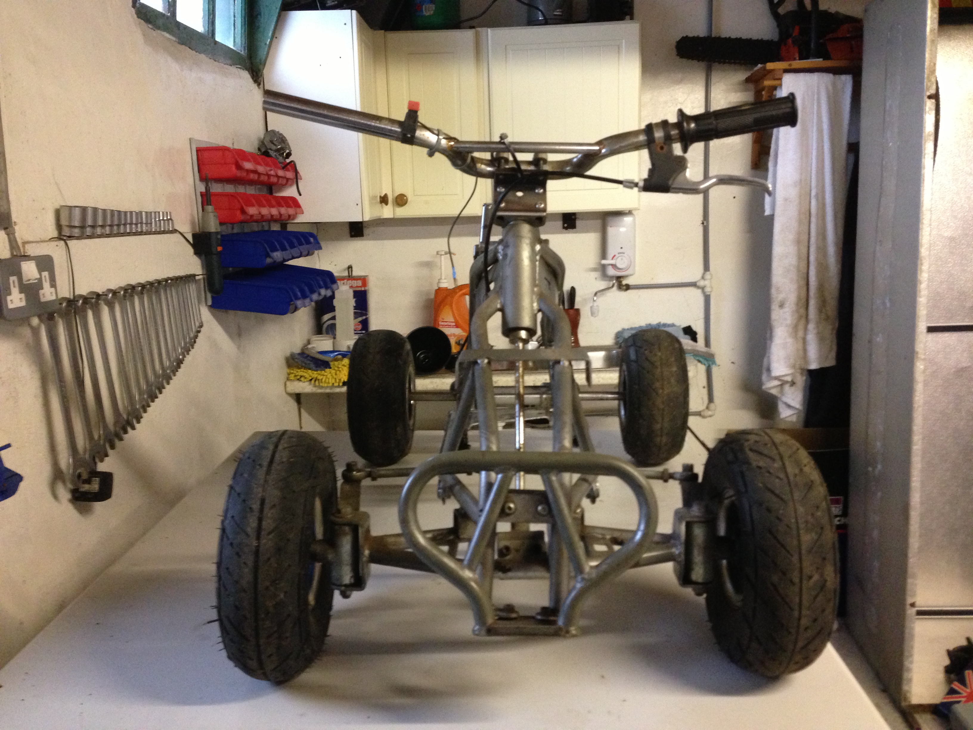
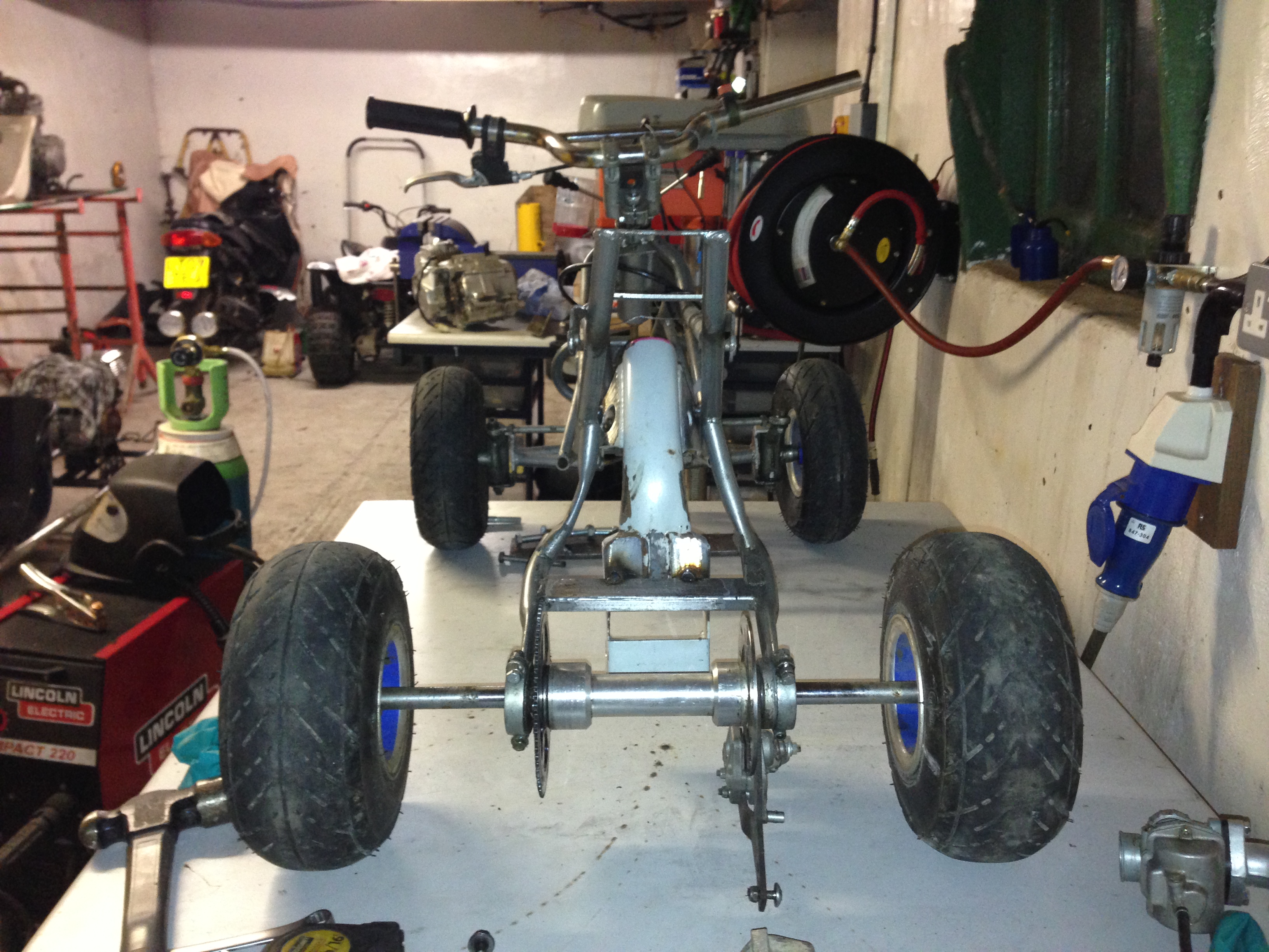
Back:
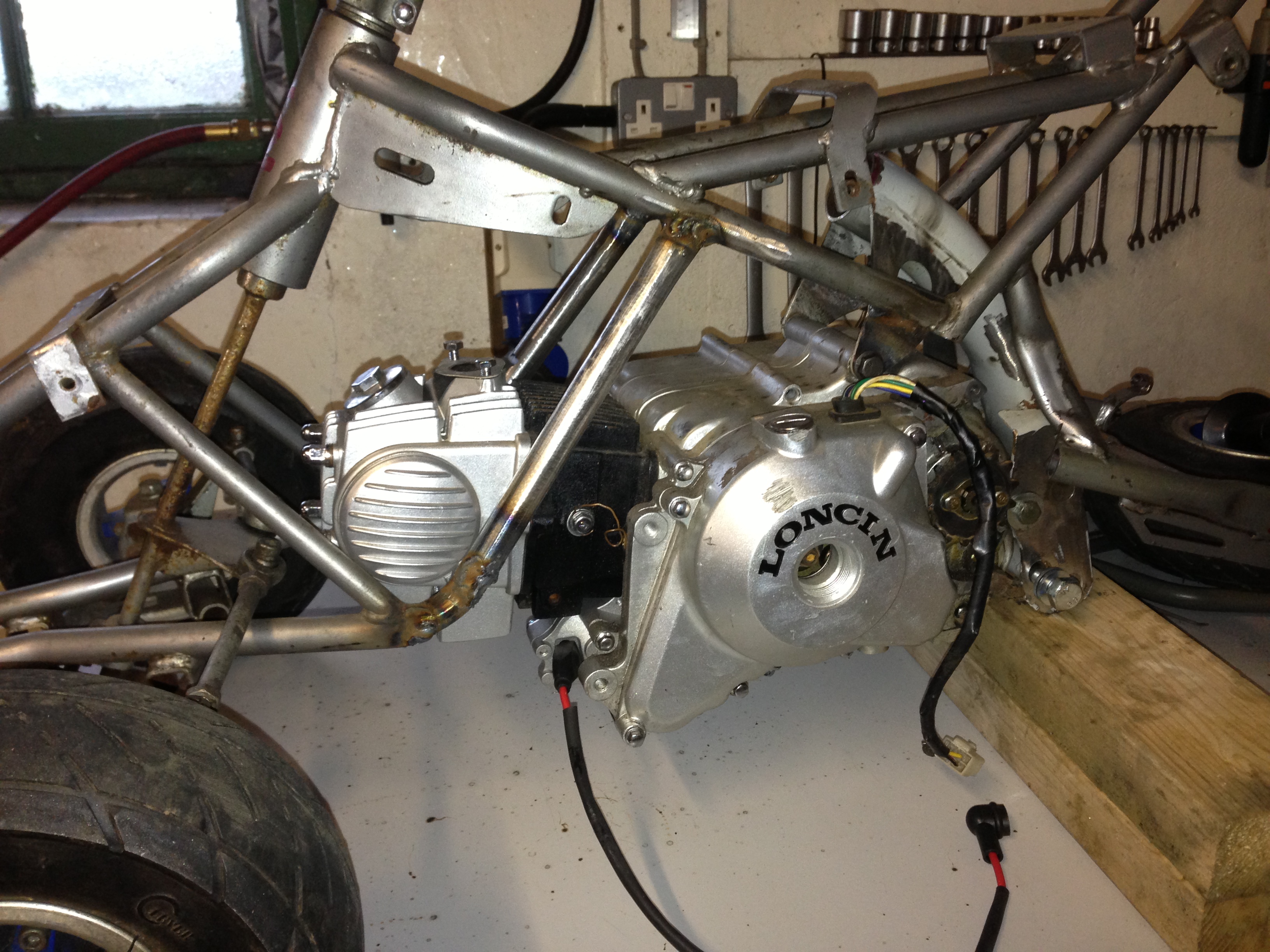
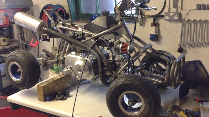
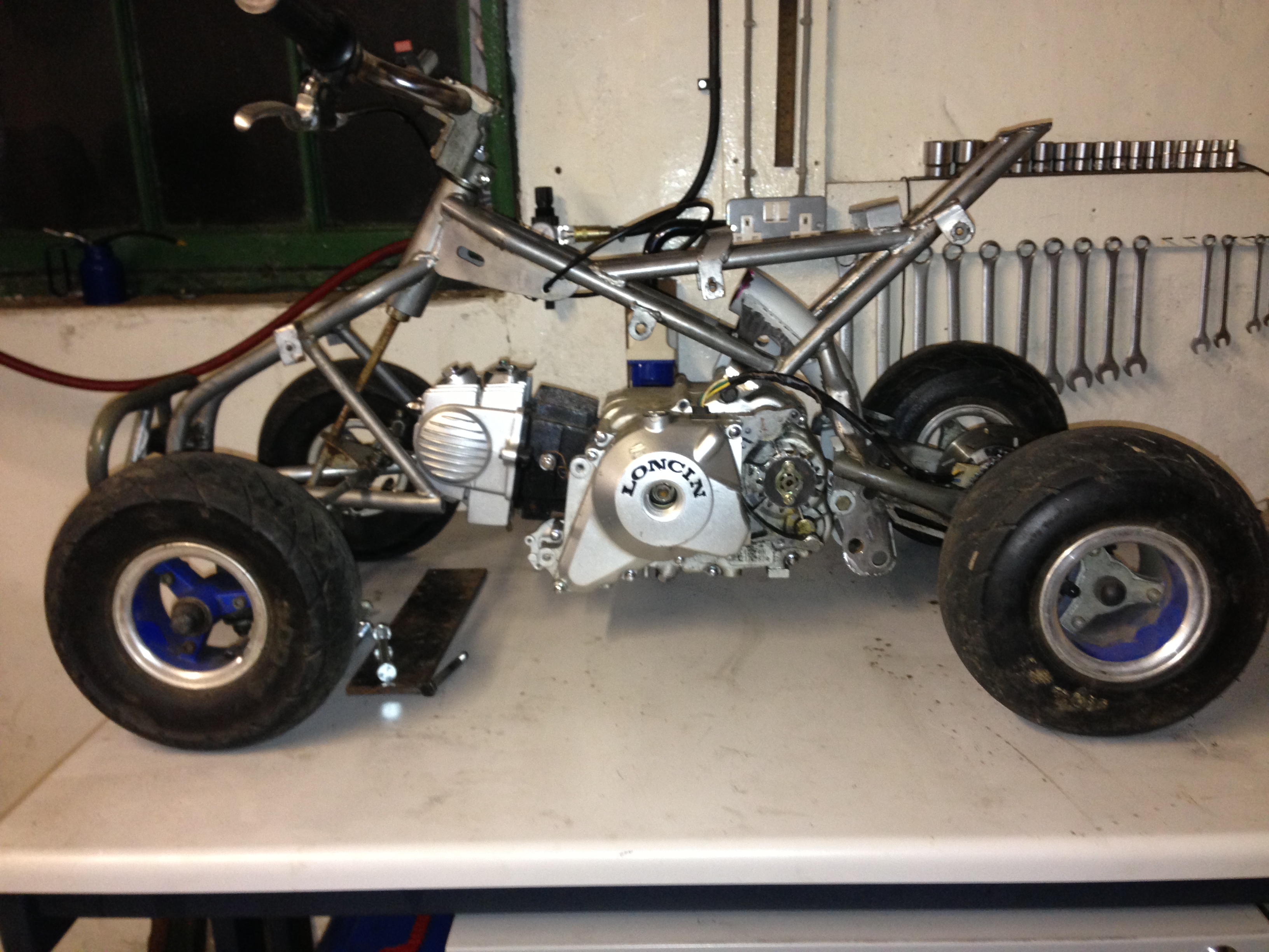
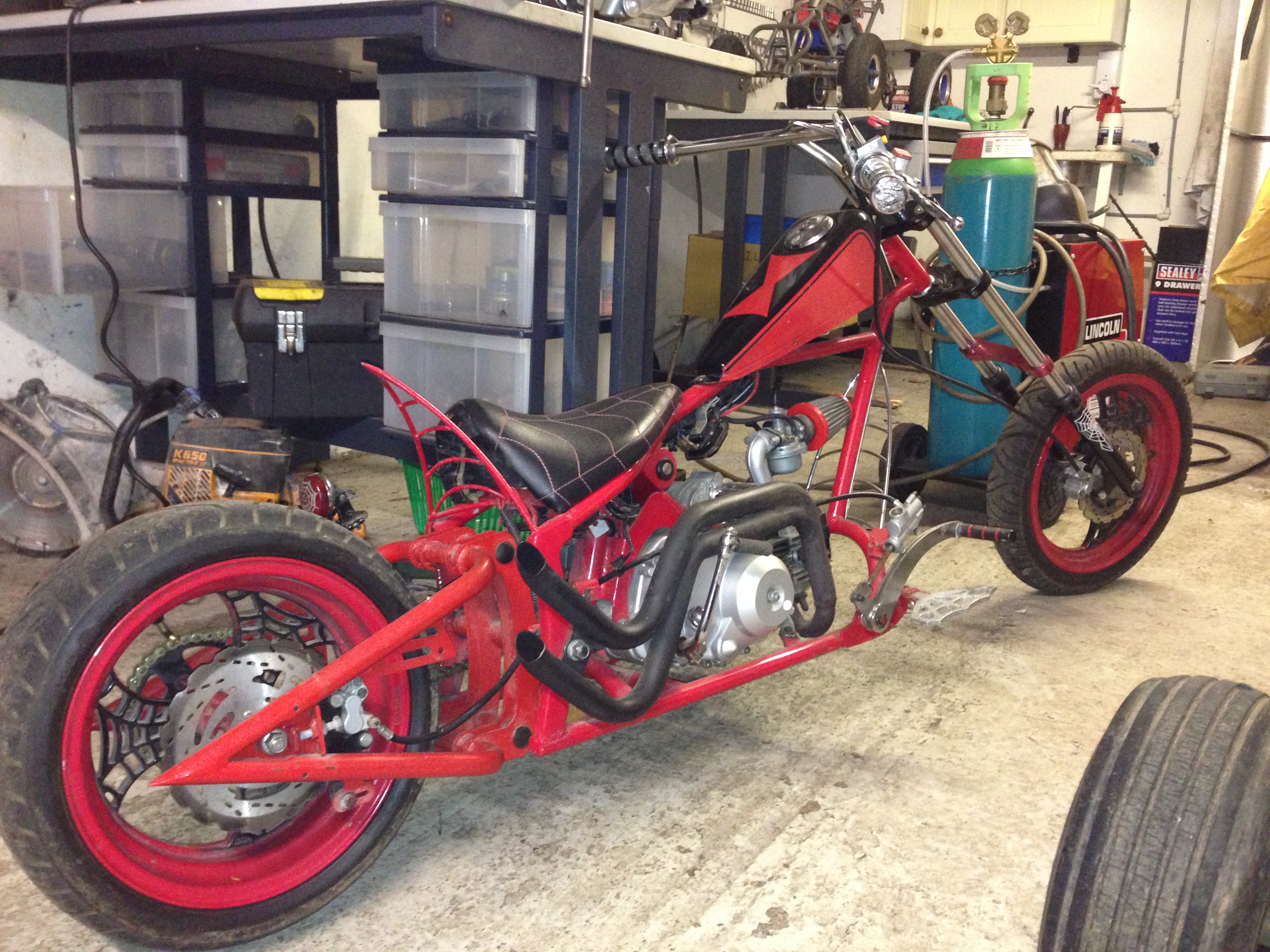
Which left me with:
the engine is so easy to lift in and out, you just lift the quad over it roughly, then hand-ball it in:
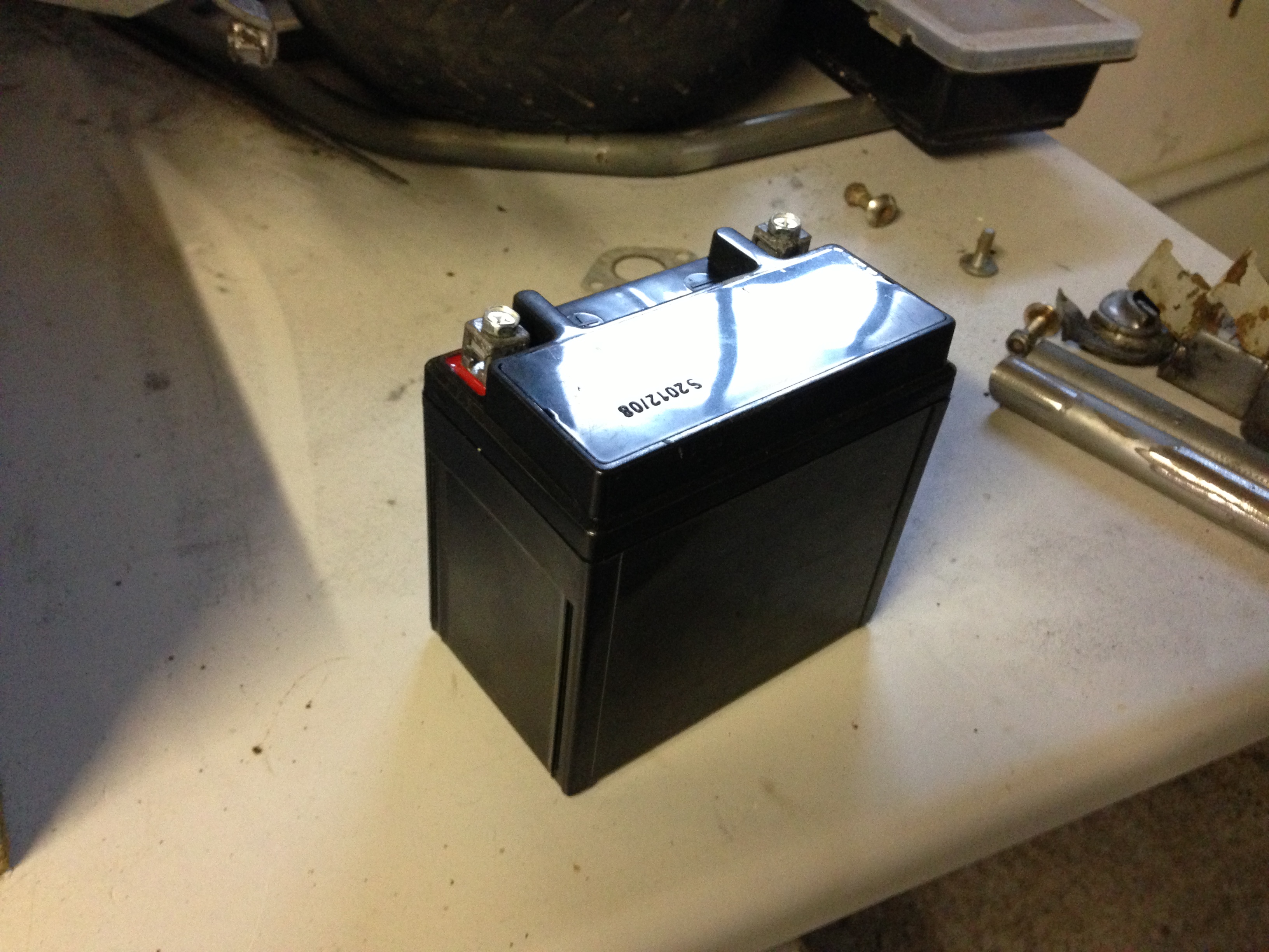
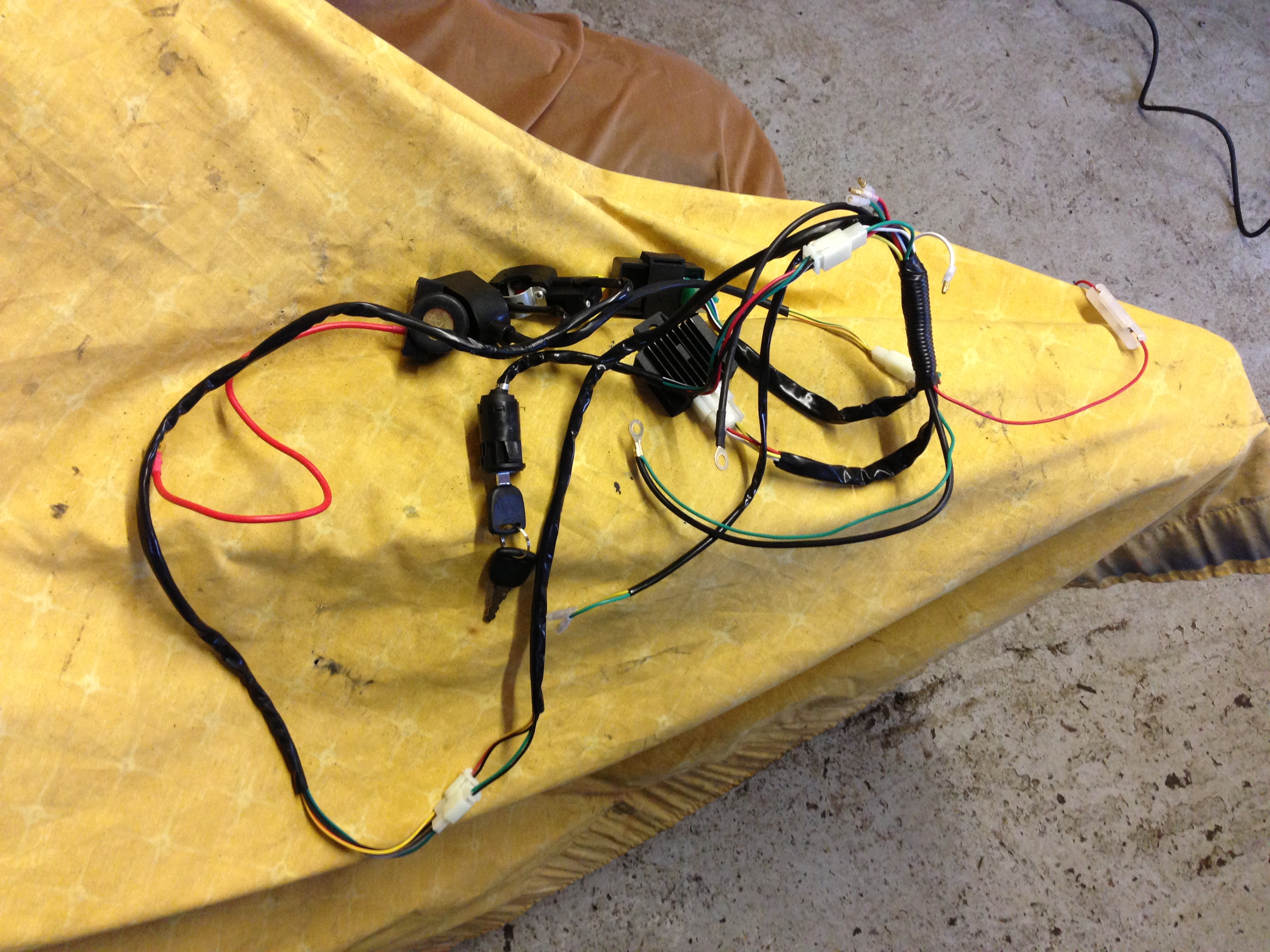
So the couple hours I worked on it on monday, I achieved what I'd set out to do, and mount the engine. I've still to fully weld the pieces in, and I've a piece of angle to use to mount the backbone properly yet. I'll be working on it today (its 1a.m. here in the UK) in the afternoon so hopefully I'll start looking at the front of the frame and the footboards. I've ordered a new wiring loom, starter motor, carb spinner and a couple of other little bits which won't be here for a while yet anyway. I also need to find a decent, small battery to use and I'll get a new one.
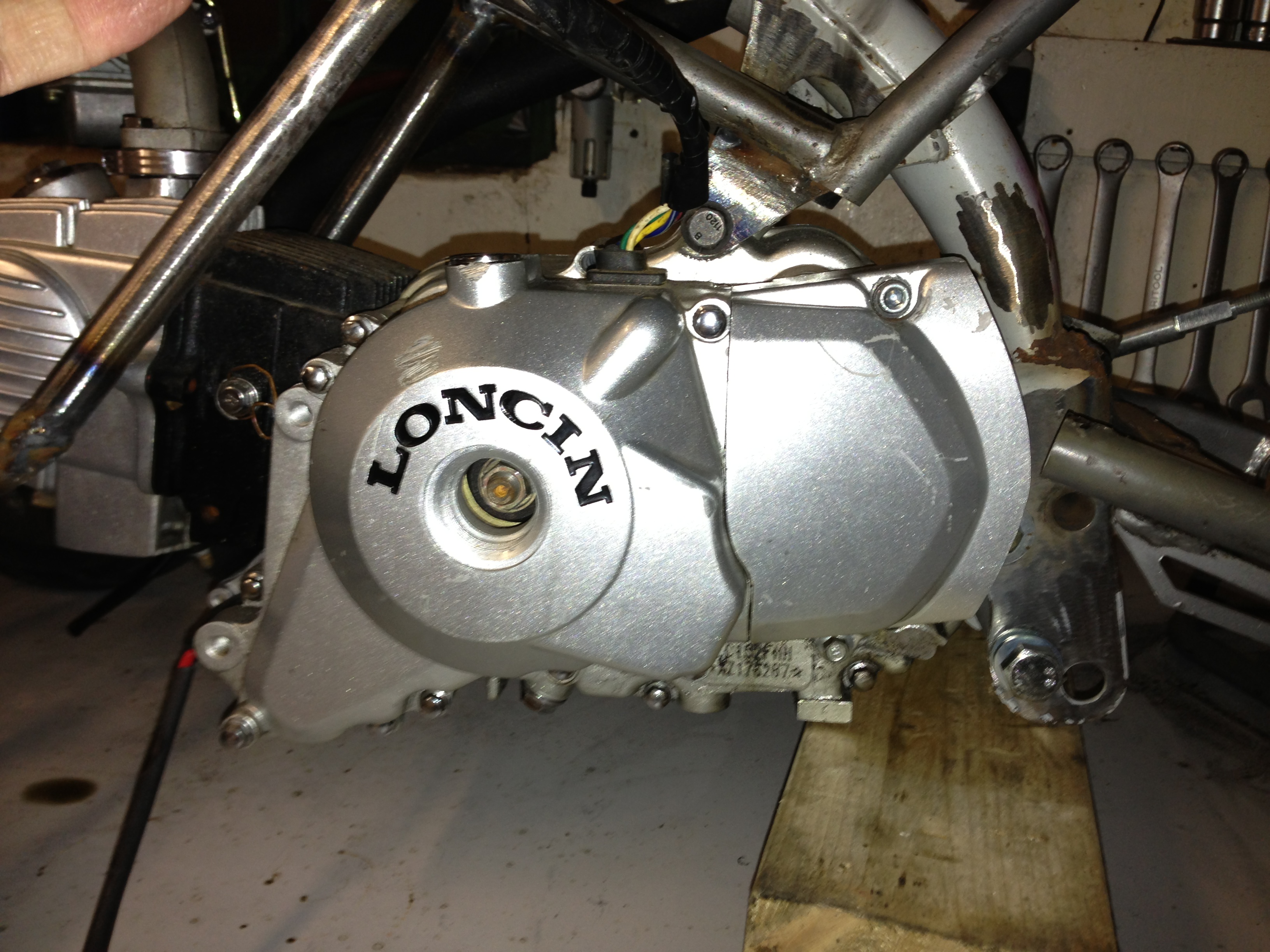
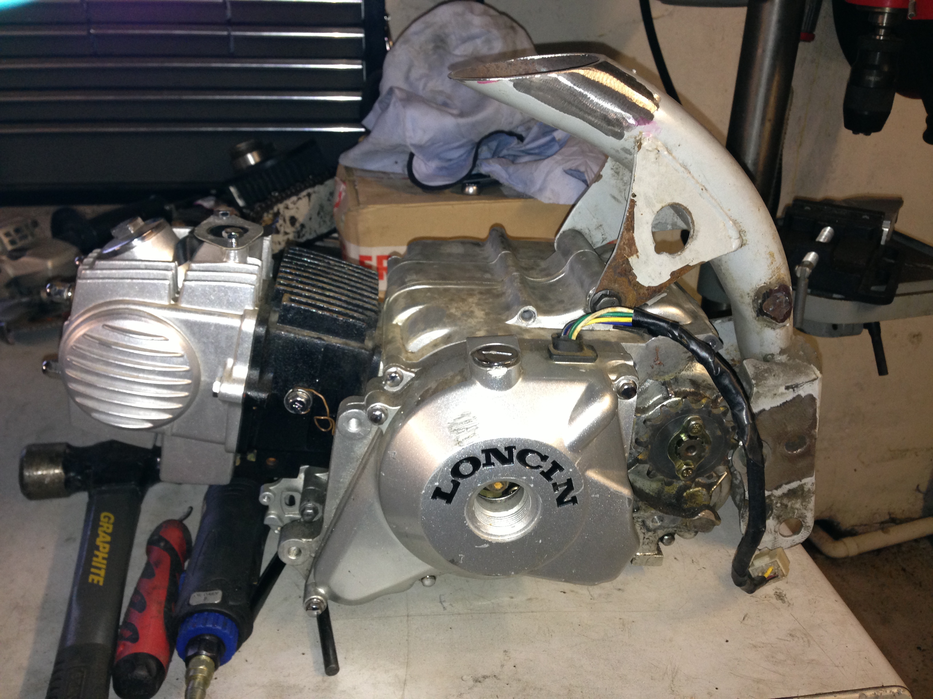
Thought I'd take a couple pics of what this engine was spare from. Its been deleted from my original post ( again, not sure why? )
Jordan
I know this isn't the perfect place for this build, but what the heck, see if anyones interested!
I've a couple miniquad chinese piece of crap things for fun for a few years. Mainly for little tracks we make here and there but moreso for when it ices over - they're too much fun!
Aside the awful welding, the plastics that dont fit and trying to stop the carbs sucking in dirt somehow these quads are still great fun!
So, I wanted to re-vamp my favourite early blata replica quad with a bit more power and better reliability, heres what I started with yesterday afternoon:
started by cutting the original engine mount plate out and the surrounding steelwork to try to massage the 110cc engine into place:
Its tight! But do-able:
Blocked the engine up into place to give me an Idea of ride Height and how to mount the engine:
Which led to me realising the easiest way would be to cut up a spare pitbike frame for its mounts:
This isnt going to be a thing of beauty by a long stretch of the imagination, I just want it done asap so I can go out on the ice when it arrives!!!
Yesterday/Monday I did some more work on the quad, I started by shaping the backbone piece I cut from the spare frame:
I had mitred and shaped the top of the backbone to match the angle the seat mounting flats ran at but I ended up just chopping that away as I dropped the engine a little further to gain more clearance for the carb.
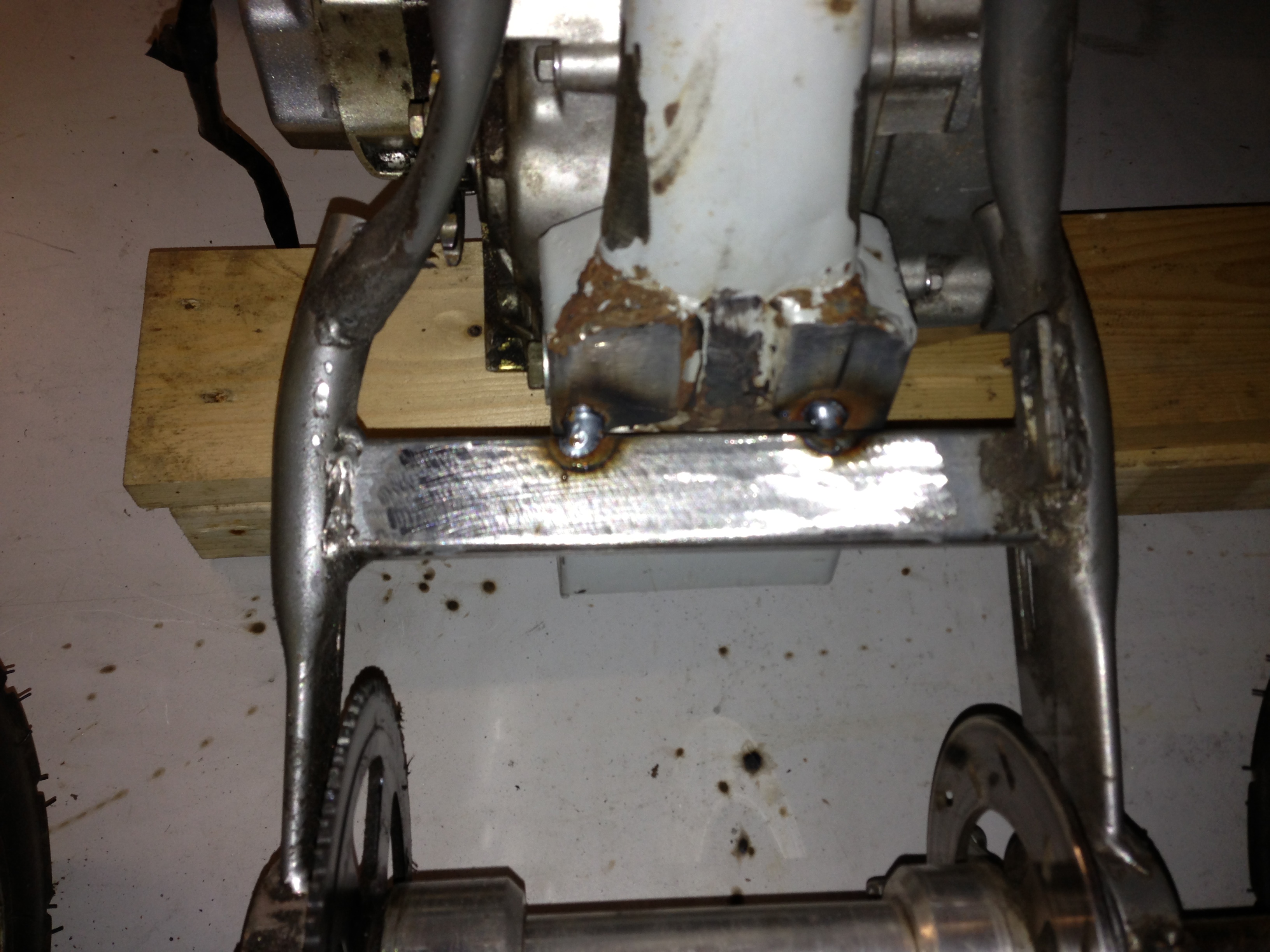
I sat the engine back in place and marked areas that would intersect frame positions where I could tack the backbone into place:
The very back of the original back-bone happened to sit parallel to this rectangular section:
and the two brackets that came off the backbone for the top engine mount touched the insides of the quad frame:
After that, I took the engine and backbone back out to clean up the areas I'd weld to on the frame and the backbone. At the same time I took the opportunity to neaten up the backbone a little of all the original pieces that were on it that I wasn't going to use and wouldnt have access to cut off after. weight saving ftw lol. I was hoping to not have to remove the rear swing-arm assembly but in order to fully prep the area I had to ( no pics ). After that, I just put the engine back in place, and tack welded the back-bone in.
Left side:
Right Side:
Back:
Which left me with:
the engine is so easy to lift in and out, you just lift the quad over it roughly, then hand-ball it in:
So the couple hours I worked on it on monday, I achieved what I'd set out to do, and mount the engine. I've still to fully weld the pieces in, and I've a piece of angle to use to mount the backbone properly yet. I'll be working on it today (its 1a.m. here in the UK) in the afternoon so hopefully I'll start looking at the front of the frame and the footboards. I've ordered a new wiring loom, starter motor, carb spinner and a couple of other little bits which won't be here for a while yet anyway. I also need to find a decent, small battery to use and I'll get a new one.
Thought I'd take a couple pics of what this engine was spare from. Its been deleted from my original post ( again, not sure why? )
Jordan
Last edited:
")