weird wiring issues

Mini Dirt Bikes & Pit Bikes Forum

Help Support Mini Dirt Bikes & Pit Bikes Forum:

This site may earn a commission from merchant affiliate links, including eBay, Amazon, and others.

gros21

Well-Known Member
Joined
Aug 2, 2013
Messages
97
Reaction score
0
ok this bike wiring is a nightmare. my recfier was orginally a 5 wire then swapped for a 4 wire which only 3 wires are run to.

what would the 4th wire be for? also what would cause teh head light and the parker to blow? they are normally just run unregulated arn't they and feed of the yellow wire before it goes to the reg. the pic of the adaptor is from my reg.

i cant find the correct engine wiring diagram

engine wiring colours are
pink
green/red
green/white
red/white
yellow.


has your engine got an outer rotor igntion kit on it, is it a GPX ?
and what cdi are you using ?


the bottom pic is your regulator plug ? with the lock tab at the top,
top left terminal is to battery positive,
top right needs to be linked to the bottom left, from the lighting coil
bottom left goes to stator lighting coil
bottom right is to battery negative/earth
 
the reason for asking what ignition stator/rotor is on it is because with those wiring colours it could be for a DC fired cdi unit
the 8 pin unit used on the Daytona/Lifan 150's

i can see in the 4th pic i think it was, a 5 pin A/C fired cdi plug on your loom, with 2 wires cut,
and the black w/yellow(+) and the green(-) for the ignition coil next to it.


you might need to take the l/h cover off the stator/sprocket and post up a pic so i know what you are running?


and your other question in the 1st post, that 4th wire that's cut on the regulator/rectifier wiring plug is the exciter wire, to turn on the reg/rect and recharge the battery
 
Last edited:
The top pic shows the wiring out of stator.
My bike has a full electrics system. But stator must only have one output (yellow) as 1st pic shows it's jointed to a black wire which is lighting.

Motor is a terra moto a early yx125 donk.

Bottom pic shows reg wiring top is old system bottom is 3 wires on new system.
 
yes,

how many pin cdi are you running ?
and can you post a picture of the stator/rotor too please ?
 
It's a bigger than normal cdi. Will do this arvo/night
 
Looks like wiring issues were due to faulty speedo. But still don't know why rectifier has only 3 wires at it
 
sorry, cant help you with the reason why someone has butchered your loom ?
but i agree, it is a huge mess, added on extra's that aren't needed, extra joins here and there, bad joins....
the chinese looms are not too good, before someone modify's them,
the wires are too thin, and easily break, and the plugs/sockets have thin terminals that don't always make good contact etc


for both the front and rear lights to be blown, one of them must have failed.
the chinese tail light bulbs are a bit fragile imo,
this would then make the other light glow brighter and caused it to burn out prematurely.
were either of the bulbs black ?

(when you replace them, make sure you use a good quality bulb)


that's good that you recognize the CDI unit, makes my job easier explaining what is needed to get it running

so you have an Outer Rotor Stator unit, it uses an AC fired CDI unit

this is the basic set up pictured below


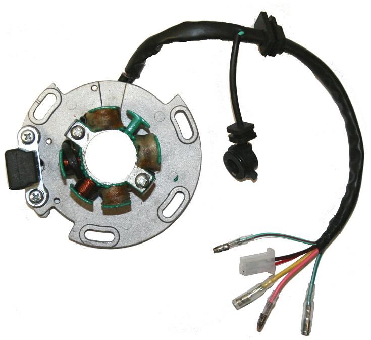
the yellow wire, is the main power from the Lighting/Charge coil on the Stator, that goes to the Voltage Regulator/Rectifier
the Regulator/Rectifier needs an exciter power wire to set it off and start working properly, sending out a 12v+ charge to the battery.
so you will need to add in a link to join the top right terminal in your Reg/Rect plug to the bottom left terminal.
they are a standard Male crimp terminal
if you look into the plug at the terminals, you will see a tiny plastic tab that holds the terminal into the plug.
push it down/away from the terminal to release the locking tab with a small flat bladed jewellery screwdriver, then the cut off yellow wire should be able to slide out the end of the plug.
now make up a new short link wire with a male spade terminal on one end, and clip it into the plastic plug
the other end of the wire needs to be joined to the yellow wire, that is coming from the stator.

doing this should have your battery charging system back up and running again.

hopefully your regulator is ok, as there are quite a few different ones available.
some are half wave 6v, some are full wave 12v, some are 1 wire hookup, others can be 4, 5 or 6 wire
there are even some better adjustable regulators available too.
you bought another new regulator iirc ?


now onto the ignition system,
do you have the big black 8 pin plug that goes into your cdi ?

the wiring colours used on the other end of these are sometimes different, and wont match up

here is a wiring diagram that should help you set it up to work


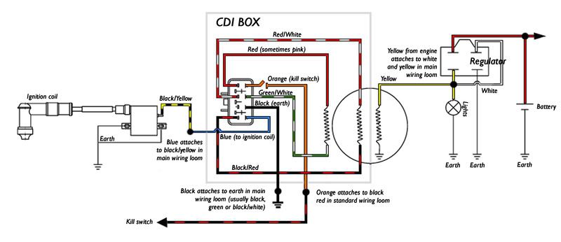
if you need any more help with it, just let me know and i'll try and guide you through it.

cheers, craig
 
Last edited:
That's my cdi 8 pin.

My reg does not have a white pin connected. I' presume I'm right to just join it to yellow wire.

Now he has ran a black wire directly to feed supply for lights. That joins onto stator yellow wire which then then goes to reg. which seems to be ok accourding to pic.

Now with out the white reg wire joined to yellow at reg would of that caused both bulbs to blow (headlight high and Parker)

Bike ran and was fine other than no lights and no
Back light on dash. Also netural light came on in 1st. But as that's another dash related issue I will wait till I get my new dash. Old one was water logged and had a bit of damage.

Bike will go for Rwc with this engine the. Get a much bigger engine.

Were would one find an assortment if plugs such as those found in the wiring loom??as if
Love to slowly rewire the lot.


Also with new engine comes a new cdi does the cdi matter much? Eg can I leave current one in there?
 
Oh what wire on stator will be netural switch and when in netural what should I expect it to eg go to earth or what.

I may remove that ratty reg adaptor and make my own and just use insulated female spades and plug it directly to the reg.
 
green with red stripe is the neutral from the stator wiring, and it provides an earth when in neutral.


you can get a few different waterproof plug/sockets from auto parts places, ebay etc
http://www.ebay.com.au/itm/4-Way-Ge...hicles_CarParts_SM&hash=item1e78ab86de&_uhb=1
http://www.ebay.com.au/sch/i.html?_...1313&_nkw=waterproof+connectors&_sacat=131090


with the white wire missing from the reg/rect, it most likely would not have put 12v out to charge the battery
a blown bulb is more likely to have blown the other bulb, due to extra power going though it, especially at higher rpms
the female connector in this set will suit the reg/rect
http://www.ebay.com.au/itm/4-Pin-Co..._Parts_Accessories&hash=item5d31d9d10c&_uhb=1


the CDI needs to match the Stator, otherwise it can damage the CDI, and or short out the stator windings
 
Last edited:
Ok so it's pointless relooming whole bike till I have new engine. Incase stator or cdi is different.

Reg/rec won't matter as all it does is convert stator power into 14.4vdc
What kind of raw power does a stator put out? Eg will I need to be carefull Incase I want to run LEDs or I spose even how my new dash is powered.

Also what does the battery run then? If all lighting is off yellow stator wire pre reg/rec?
all over the joint.. will reuin anything thats attached just run a regulator before these devices
 
To easy there is a diode in my wiring loom someware as well.

Why wouldn't I just run my lighting of my battery? As
I have led indicators and tail light ima touch worried about cooking them.

To do that i would just dissconnect it from
Stator wiring and well take it directly to the battery. Could also tea off a Perment 12v connection as
My new dash will have a Perment 12v feed to keep settings

The old dash did not (same dash as Sachs madass)
 
the head and tail light only run directly off the lighting/charge coil in the stator, it will give off a dim light at idle, and get brighter as you rev it.


battery runs ignition switch, horn, indicators and dash, most 12v systems would be lucky to get to 13v at full rpm


when i rewired my sons' buggy,
i have set it up to run the lights, horn, indicators, gauges etc off the battery.
it gives it a more consistent light/power at any time.
 
Kool so the pic intage previous page is incorrect. Lights should be off battery.

Also playing with netural switch last night yep deff comes
On in 1st so I'll take the switch out and spin it.
 
no, they are wired up standard off the lighting coil, and are AC powered.
so whatever voltage it puts out, goes straight to the lights.


i wired the Dune Buggy up different to the diagram above, i used 12v DC,
that way if i need lights for whatever, the buggys' engine didn't need to be running.

iirc,
most of the Honda XR 250,350,400 , and Yamaha DT/IT 175,200,250,465 etc range only had Head an Taillights when the engine runs, and use 12v or 6v AC bulbs.


with your neutral switch,
there are 4 sorts available of switches available, depending on what the engine is used in/for.
there is a neutral indicator switch for 1N234 (1 down 3 up)
they are usually wired up as a start in neutral only (front clutched 110/125's etc)
and then there's a different one used for N1234 gearboxes.
some switches are only for neutral, and run one contact/wire, they have a green w/red stripe wire.
and the shape of the rubber switch contact will only fit into the casing one way.
the brass contact on the end of the shift drum may have moved in yours' though ?
remove the rubber switch contact, there should be a 10mm headed bolt that can be loosened and the contact moved.

others are a gear indicator and run a 5 contact/wire switch,
the pink wire is for 1st gear,
the green w/red stripe is for neutral,
the blue w/red stripe is for 2nd,
the green w/black stripe is for 3rd,
and the light blue w/red stripe is for 4th
 

Latest posts

Back
Top